#capacitors


Thor’s hammer to crush materials at 1 million atmospheres
Sophisticated features may influence eventual Z-machine rebuild
A new Sandia National Laboratories accelerator called Thor is expected to be 40 times more efficient than Sandia’s Z machine, the world’s largest and most powerful pulsed-power accelerator, in generating pressures to study materials under extreme conditions.
“Thor’s magnetic field will reach about one million atmospheres, about the pressures at Earth’s core,” said David Reisman, lead theoretical physicist of the project.
Though unable to match Z’s 5 million atmospheres, the completed Thor will be smaller – 2,000 rather than 10,000 square feet – and will be considerably more efficient due to design improvements that use hundreds of small capacitors instead of Z’s few large ones.
Remarkable structural transformation
This change resembles the transformation of computer architecture in which a single extremely powerful computer chip was replaced with many relatively simple chips working in unison, or to the evolution from several high-voltage vacuum tubes to computers powered by a much larger number of low-voltage solid-state switches.
Post link

So let’s take a quick look at how varying frequency changes the performance of a circuit. The circuit above has a capacitor, inductor, and resistor in series. We’d like to know what the output, Vout, is as a function of frequency.
We can get Vout just as we’d normally do with a voltage divider. Since we’re dealing with inductors and capacitors, frequency will show up here.

We can manipulate this a little to get it into the standardized form we looked at earlier and make the substitution of s for jω. We’re left with an equation that describes the behavior of Vout with regard to frequency.

Post link
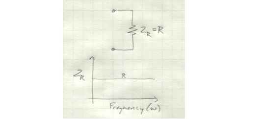
We’ve spent a lot of time talking about the impedance of resistors, capacitors, and inductors. We know that the impedance of inductors and capacitors is dependent on frequency, but we haven’t really explored what that means.
A resistor presents the same amount of resistance regardless of frequency.
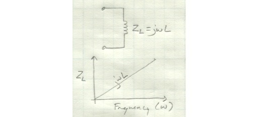
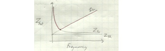
For an inductor, the impedance increases linearly as frequency increases.
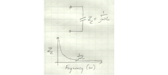
For a capacitor, the impedance decreases rapidly as frequency increases.
So what about a circuit which includes all three elements? Its combined impedance will be the sum of the individual impedances. You’ll get an overall impedance that is high at very low frequencies, becomes low at a slightly higher frequency, and then gradually increases again.
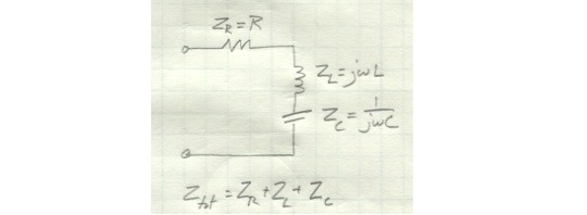
In other words, this thing is basically a filter that blocks very high and low frequencies and lets signals of lower-midrange frequencies through with relatively little difficulty.
If we rearrange equation a little, we get something that’s kind of ugly, but fairly compact. We’ll substitute s for jω - we’ll talk about why later on, but for now, just know that s=jω. We’ll be seeing a lot more of this equation in future articles.