#motorola 68k

Full Speed Ahead … Finally
I have been building my 68030 computer around a 25MHz-rated part, so that has always been my target. My original wire-wrap prototype initially ran at half that, but as I continued to expand the project, the best I could manage was 6MHz. Eventually, the whole thing got so unstable I had to abandon plans to continue adding FPU, DRAM, IDE, etc.
I do still want to add those parts to the project, to learn more about working with them. That’s why I ordered the custom PCBs — I was hoping a PCB would be a more stable platform for future expansion and allow me to finally run the machine at the 25MHz target.
Once I got the new PCB prototype working I tried again with a 25MHz oscillator (my new glue logic no longer divides the clock like my original).
It didn’t work.
In fact, at 25MHz it failed in the same way it always had on the old wire-wrap prototype. It seemed 12 MHz was my limit.
Or was it? Maybe I just had a bad oscillator. Perhaps a new one would work better?
A ridiculous line of thought, given that the 25MHz oscillator I had did indeed run the computer at one time. But, I did want to see how fast I could get it to run, and there are some respectable speeds between 12MHz and 25MHz. So I placed an order for a few oscillators, 16MHz, 20MHz, 24MHz … I also stocked up on some common resistors and capacitors to make the most of the shipping fee.
Got the new parts in, threw on the 24MHz oscillator and … nothing. It didn’t work.
There is a problem I noticed when I did my original troubleshooting on this PCB — some of the wired-or signals had very slow rise times. I don’t have a proper oscilloscope, so it’s hard to tell sometimes if analog problems like that are measurement error or induced by stray capacitance of the measurement leads. But, the 8kΩ resistor networks I had gotten from surplus to use as pull-ups on this project were a bit high. Perhaps a lower-value pull-up resistor might help here.
Among the resistors I ordered were some 4.7kΩ and 1kΩ resistor networks. 4k7 is a fairly standard pull-up value, and some rough math had shown 1k might be a good value for this project. So I swapped out the 8k resistor networks for the new 1k networks and gave it a shot. It still ran without issue at 12MHz…
And at 16MHz.
And at 20MHz.
And at 24MHz.
And at 25MHz.
And at 32MHz.
And at 40MHz.
My MC68030 rated for 25MHz was running BASIC stable at a 60% overclock. Even the RAM was overclocked at this point, with cycles reduced to 50ns for SRAM rated for 55ns. It would seem that all this time my choice of pull-up resistor value had as much or more to do with my speed limits as the method of prototyping.
It wasn’t perfect though, and as soon as I added my SE-VGA card back into the mix it would no longer successfully load BASIC at 40MHz. It did however run just fine at 32MHz, even with the SE-VGA card.
Ludicrous Speed
In the years since I started this project I acquired another 68030 CPU — a 40MHz-rated 68EC030 (the EC units lacking the on-board MMU). I’m sure you can see where this is going.
First, I needed to modify my glue logic. RAM access cycles were going to need another wait state, ROM another two. While I was at it, I created a new cycle specifically for my SE-VGA card, with three wait states. Since my UART (68B50) is actually rated for 2MHz, and my timing was originally factored for 1MHz with a 25MHz base clock, I left the UART timing alone to push it closer to its rated speed. All-around, the new timing should support up to 50MHz base clock.
New logic, everything ran fine at 32MHz. Swapped in the EC030 and no problems. Time to see how fast it will go.
40MHz, no sweat
50MHz, still running cool
56MHz, no problems
I’m out of oscillators. My 68030 homebrew, with a 40MHz-rated EC030 is running reliably at 56MHz, a 40% overclock. Even the SE-VGA card is working, and much happier with its custom timing added to the glue logic.
I’ve been using a simple Mandelbrot rendering BASIC program as a benchmark. On my original 6MHz 68000 build, this program takes around 9 minutes to complete. When I first ran it on the 68030, running at 12MHz, with cache disabled, and BASIC in 8-bit ROM, it took just under 5 minutes. Now, with BASIC running from RAM on the 32-bit bus, L1 cache enabled, and CPU at 56MHz, the Mandelbrot program completes in 14 seconds. That is an incredible performance increase for a simple homebrew computer.
It does generate some heat now, so I added a small heatsink to the CPU to be safe. Current consumption for the system is up 300mA just from raising the clock speed.
Motorola originally sold 68030 CPUs rated as high as 50MHz. I wonder if my later production units just benefit from what they learned pushing the architecture that high, or if it’s reflective of what the CPU can handle in general. Could I push a 50MHz part up 40%? A 70MHz 68030 homebrew certainly would be interesting.
@avics1967 asked:
Hi, which signals did you pull up? Care to share the schematics?
I put pull-up resistors on all CPU active-low control input signals, especially those which might be driven by multiple devices in wired-or configuration. In this case, it’s likely to be the bus cycle termination signals ( !DSACKxand!STERM ) that were causing trouble with the weaker pull-ups.
I’ve got the schematic on GitHub.
Full Speed Ahead … Finally
I have been building my 68030 computer around a 25MHz-rated part, so that has always been my target. My original wire-wrap prototype initially ran at half that, but as I continued to expand the project, the best I could manage was 6MHz. Eventually, the whole thing got so unstable I had to abandon plans to continue adding FPU, DRAM, IDE, etc.
I do still want to add those parts to the project, to learn more about working with them. That’s why I ordered the custom PCBs — I was hoping a PCB would be a more stable platform for future expansion and allow me to finally run the machine at the 25MHz target.
Once I got the new PCB prototype working I tried again with a 25MHz oscillator (my new glue logic no longer divides the clock like my original).
It didn’t work.
In fact, at 25MHz it failed in the same way it always had on the old wire-wrap prototype. It seemed 12 MHz was my limit.
Or was it? Maybe I just had a bad oscillator. Perhaps a new one would work better?
A ridiculous line of thought, given that the 25MHz oscillator I had did indeed run the computer at one time. But, I did want to see how fast I could get it to run, and there are some respectable speeds between 12MHz and 25MHz. So I placed an order for a few oscillators, 16MHz, 20MHz, 24MHz … I also stocked up on some common resistors and capacitors to make the most of the shipping fee.
Got the new parts in, threw on the 24MHz oscillator and … nothing. It didn’t work.
There is a problem I noticed when I did my original troubleshooting on this PCB — some of the wired-or signals had very slow rise times. I don’t have a proper oscilloscope, so it’s hard to tell sometimes if analog problems like that are measurement error or induced by stray capacitance of the measurement leads. But, the 8kΩ resistor networks I had gotten from surplus to use as pull-ups on this project were a bit high. Perhaps a lower-value pull-up resistor might help here.
Among the resistors I ordered were some 4.7kΩ and 1kΩ resistor networks. 4k7 is a fairly standard pull-up value, and some rough math had shown 1k might be a good value for this project. So I swapped out the 8k resistor networks for the new 1k networks and gave it a shot. It still ran without issue at 12MHz…
And at 16MHz.
And at 20MHz.
And at 24MHz.
And at 25MHz.
And at 32MHz.
And at 40MHz.
My MC68030 rated for 25MHz was running BASIC stable at a 60% overclock. Even the RAM was overclocked at this point, with cycles reduced to 50ns for SRAM rated for 55ns. It would seem that all this time my choice of pull-up resistor value had as much or more to do with my speed limits as the method of prototyping.
It wasn’t perfect though, and as soon as I added my SE-VGA card back into the mix it would no longer successfully load BASIC at 40MHz. It did however run just fine at 32MHz, even with the SE-VGA card.
Ludicrous Speed
In the years since I started this project I acquired another 68030 CPU — a 40MHz-rated 68EC030 (the EC units lacking the on-board MMU). I’m sure you can see where this is going.
First, I needed to modify my glue logic. RAM access cycles were going to need another wait state, ROM another two. While I was at it, I created a new cycle specifically for my SE-VGA card, with three wait states. Since my UART (68B50) is actually rated for 2MHz, and my timing was originally factored for 1MHz with a 25MHz base clock, I left the UART timing alone to push it closer to its rated speed. All-around, the new timing should support up to 50MHz base clock.
New logic, everything ran fine at 32MHz. Swapped in the EC030 and no problems. Time to see how fast it will go.
40MHz, no sweat
50MHz, still running cool
56MHz, no problems
I’m out of oscillators. My 68030 homebrew, with a 40MHz-rated EC030 is running reliably at 56MHz, a 40% overclock. Even the SE-VGA card is working, and much happier with its custom timing added to the glue logic.
I’ve been using a simple Mandelbrot rendering BASIC program as a benchmark. On my original 6MHz 68000 build, this program takes around 9 minutes to complete. When I first ran it on the 68030, running at 12MHz, with cache disabled, and BASIC in 8-bit ROM, it took just under 5 minutes. Now, with BASIC running from RAM on the 32-bit bus, L1 cache enabled, and CPU at 56MHz, the Mandelbrot program completes in 14 seconds. That is an incredible performance increase for a simple homebrew computer.
It does generate some heat now, so I added a small heatsink to the CPU to be safe. Current consumption for the system is up 300mA just from raising the clock speed.
Motorola originally sold 68030 CPUs rated as high as 50MHz. I wonder if my later production units just benefit from what they learned pushing the architecture that high, or if it’s reflective of what the CPU can handle in general. Could I push a 50MHz part up 40%? A 70MHz 68030 homebrew certainly would be interesting.
Combining Projects

My 68030 homebrew computer is coming along nicely. It’s running stable at 12MHz, I’ve got BASIC running, I can transfer programs to it from another computer. I think it’s ready to take to the next local retro computer meetup. I just need some flashy demo program.
Well what would be better than giving it a video output? And it just so happens that I have a perfectly good video card designed for the 68k bus just sitting around.
I added my SE-VGA card to my 68030 homebrew.
I already had expansion bus ports on my 68030 protect, I just needed an adapter for the 68000 socket & bus.


I threw together a card that stacks on top of my 68030 and connects to its expansion bus. The SE-VGA card plugs into the adapter card. A couple TTL chips (a 74HCT32 and a 74HCT14) provide the discrete !UDSand!LDS signals for the 68000 bus on the SE-VGA, as well as a power on reset circuit. Jumpers for the SE-VGA are set for 2MB, since that’s the amount of RAM I have on the 68030.
And that’s all it took. I didn’t have to update logic for the SE-VGA or glue logic for the 68030. Updating the video output just requires writing to the video buffer addresses that a Mac SE would use with 2MB of RAM (0x1FA700)
I can use the PEEKandPOKE functions in BASIC to write to the video buffer, but this is painfully slow. I’ve started writing some helper functions that can be run using the BASIC CALL function to handle some screen drawing tasks in Assembly. These make drawing to the screen a much more reasonable task.

This isn’t the direction I intended to take this project (the goal has always been multi-user *nix with multiple serial terminals), but it’s been fun to play with. Computer video always seemed like black magic. It’s been fascinating to build it from the ground up and see how it all works.
Serial Expansion
TSMON, the ROM monitor I’m running on my 68030 board, is designed to use two serial ports — one for the primary console, and one for an attached development computer. I’ve only ever used it with a single serial port. It would be useful to have a second for loading programs straight into memory. My 68030 board only has a single UART footprint, but why should that stop me?


I built a breakout board that plugs into the socket for the existing UART and adds a second. It holds a pair of 6850 UARTs, a 74'139 for address decoding, and a MAX232 level shifter. I even added some jumpers to disable the second UART if necessary.
It worked without issue with just the first UART populated, and the second UART did not interfere with the first one when it was added.

I’ve updated TSMON to add back in code for the second serial port which I had previously removed. I also edited the EhBASIC VEC_IN routine to check both serial ports for data. Now I can send BASIC programs over serial from another computer then run them using a terminal connected to the first serial port on the 68030 board.
Returning to 68030 … Again
I left off with my 68030 homebrew project having just finished assembling a new PCB that was 1:1 with my wire-wrap prototype.

It did not work.
In theory, it should have been as simple as transferring all the chips from the prototype to the PCB and starting it up. Reality is never so friendly as that.
It was failing in a familiar fashion, with errors coming swiftly after startup. It reminded me of a big problem I’d had with at the beginning, before I had properly implemented the chip select signals for RAM. But I had solved that problem a long time ago, how could it be back?
Turns out I had the chip select signals for RAM routed backwards. The RAM chip for the high 8 bits of the data bus was getting the enable signal for the low 8 bits, and so on.
I dug out the glue logic, changed those four pin assignments, and burned a new CPLD and … nothing. Nothing worked. It was worse than I started and now it wouldn’t even run when I reassembled the prototype.
Back in the box it went, for months.
I finally pulled it out recently and set out to get it running, starting with all new glue logic.
The original logic was all done in the Quartus schematic builder. At the time, it was too complex for my rudimentary VHDL skills. I’ve been learning Verilog and have built some successful projects with it that are far more complicated than this glue logic. So I started from scratch, rewrote all the logic fully synchronous in Verilog.
I started testing as small and basic as I could, stepping through each piece to confirm it worked before moving on. The logic responded appropriately to signals toggled manually. The CPU was able to free run with its data bus held low and the glue logic providing the termination signals. It was able to run code from ROM.


There were of course a few odd bugs here and there in the new glue logic, but in all it progressed fairly smoothly. I started writing some test programs to test the bus and make sure I got the chip select signals right this time.

With no RAM actually connected, it failed every test just as expected. Finally, it was time to add in the RAM.

RAM tests passed. I had a working computer again! Time to dust off the source code for the TSMON monitor program and Enhanced BASIC.
TSMON loaded and ran with few problems. Similar to my 68000 build, I wrote an expansion ROM for TSMON to load BASIC from ROM into RAM before running it.

So now I’m back where I was a couple years ago — I have a homebrew 68030 running BASIC.
This time though, it’s running fairly stable at 12MHz. The old wire-wrap prototype struggled to run stable at 6MHz.
SE Exp30
 ALT
ALTI ordered some boards for my Mac SE accelerator. I’m quite pleased with how they look.
 ALT
ALT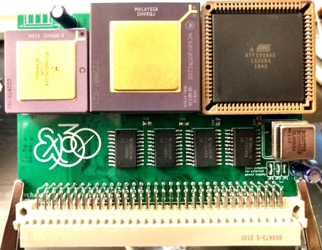 ALT
ALTAssembly wasn’t too bad. The 0805-size resistors and capacitors can be a bit fiddly to work by hand, but they’re still manageable. In all, it just took a couple hours to put together the first test board.
 ALT
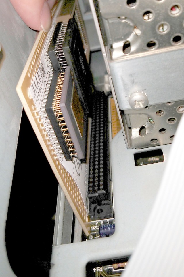
ALTIt fits in my SE with plenty of clearance between it and the floppy drive cages.
So the big question is — does it work?
 ALT
ALTOf course not! What fun would that be?
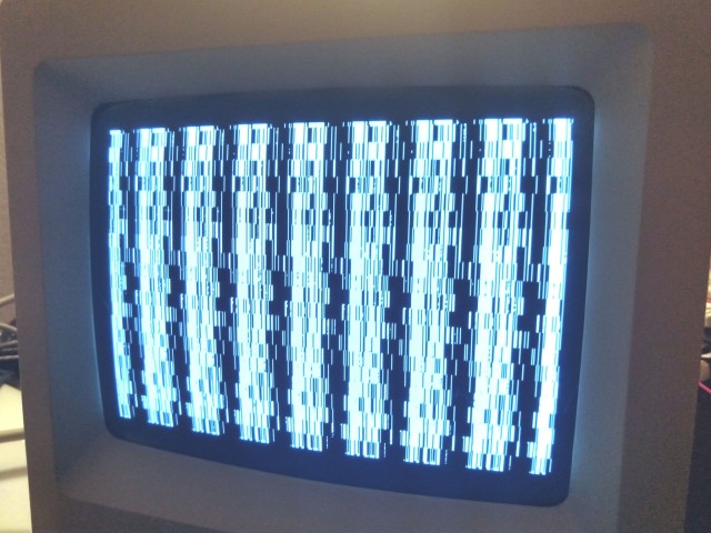
First run attempt was just a garbled screen, and not even the infamous checkerboard pattern. I didn’t expect it to be fully functional at first attempt, but that pattern is a new one.
Time for the logic analyzer.
I can see the hand-off working. The accelerator asserts the Bus Request signal to take the SE 68000 off the bus, and waits for the Bus Grant signal in response. Once the 68000 is off the bus, the 68030 is brought out of reset and allowed to take over. That much worked as expected.
Next thing to look at is whether the 68030 is starting up properly. The first thing it’s going to do is load the initial startup vector and stack pointer from ROM. These are 32-bit values, so each will take two access cycles over the 16-bit SE bus. It was getting stuck on these initial read cycles, waiting for a bus termination signal
The 68k processor family has a great asynchronous bus that relies on peripherals providing an appropriate bus cycle termination signal. Macintosh computers generate the termination signal synchronous to the system clock. What I found was the faster 68030 (running at 12MHz for testing) was sometimes ending one cycle and starting the next within a single clock pulse of the main 8MHz SE clock. The SE motherboard logic never saw the new CPU cycle begin.
My first draft of logic was largely asynchronous, and paid little attention to the system clock. But since the SE motherboard logic is synchronous and expecting 68000 bus cycles, I need my logic to better emulate 68000 bus cycles.
So I rewrote nearly all of the logic for the CPLD to roughly emulate 68000 bus cycles.
 ALT
ALTNever thought I’d be happy to see a Sad Mac error. That error means the 68030 is running enough code for the initial ROM checksum to fail. That’s quite an improvement over not even loading the initial vectors.
I’ve got a long way to go on this project, but it’s looking promising. Running any code at all is a great sign. I can already see a the next few logic bugs that need to be addressed, and I’ve found a few hardware bugs that’ll need bodge wires.
 ALT
ALTBuilding a Faster SE
The Macintosh SE was the first Mac model to support internal expansion cards, by way of its Processor Direct Slot. As the name implies, the PDS connector exposes most of the 68000 processor signals. This makes it an ideal candidate for a CPU upgrade card. Many such products were available in the early 1990s, offering faster and newer processors, cache, additional memory etc.
The Motorola 68030 is a great option for accelerating an existing 68k system. It has the same instruction set, with a few additions, so all the same code will run. It also supports dynamic bus sizing, so it can easily interface with 8-, 16-, and 32-bit peripherals. And it supported clock speeds up to 50MHz. All around, it’s a fairly easy 32-bit processor to start with, and it can be adapted to the 68000 bus with minimal additional logic.
 ALT
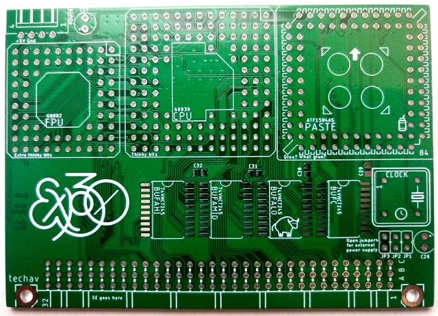
ALTSo I tried my hand at making a 68030 accelerator card for the Mac SE. It has a 68030 CPU & 68882 FPU, and uses an Atmel ATF1504 CPLD & some 74'245 buffers as glue logic adapting the 32-bit bus of the 68030 to the 16-bit bus of the 68000 and SE.
I’ve not added any cache or extra RAM. I thought it best to start small and get the basic bus translation working first. Ideally, this little card would be transparent to the OS, perhaps only needing a small init to enable the 68030 L1 cache or announce presence of the FPU.
If I can get this basic card to work, I might move on to adding L2 cache or 32-bit-wide RAM to help further accelerate the system.
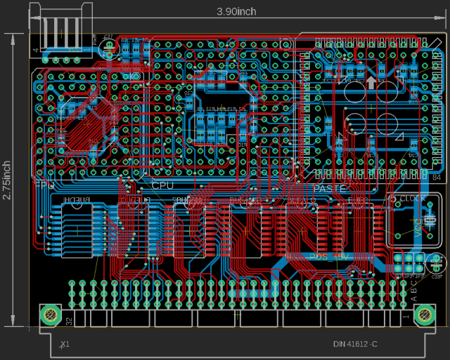
Debugging 68030 PCB

I had dared to hope that since this board was created from the same schematic and board file I had made and referenced for my wire-wrap 68030 project, that I could just move the parts over and let it run. If I was really lucky, it might even be able to run faster than the original.
I should know by now it’s never that easy.
The board does indeed run. It starts up, initializes its serial port, copies BASIC into RAM, verifies the copy, then starts running BASIC. It never gets to the BASIC ready prompt though.
Time to pull out the logic analyzer. This would certainly be easier if I had a proper logic analyzer with 64 or even over 100 channels, but there is a lot that can be learned 16 channels at a time. Watching important parts of the address bus I was able to watch it step through the BASIC initialization routines. However just before it got to the point where it would print its first carriage return, it jumped to an address I didn’t expect, and I couldn’t follow where it had gone. Shortly after, it would start accessing invalid addresses and generating bus errors.
The point where I lost it was right when it called a vector to its character print subroutine. This version of BASIC is written to be position-independent, so it has a short vector table for common I/O handlers in its global variable space. When it’s time to call one of these routines, it performs a jump operation using the vector in that table ( jsr voutp(a3)).
I could see it getting that far, recall the vector, and push its return address to stack. But where it ended up was a mystery.
This points to memory corruption somewhere, but where? I had a similar issue when I was building the prototype, before I had properly built out the RAM chip select signals, but that fix is already incorporated into this board.
I started writing some memory test routines. Unsurprisingly, long word write and read back tests all passed (after all it was loading and verifying BASIC the same way already). Byte-level tests also passed without issue. I needed something more thorough.
I put together a simple test that would write a single byte, followed by writing a long word, alternating for 16 total bytes. This would force it to write misaligned long words to confirm RAM addressing was working correctly.
It failed.
The bytes read back were all jumbled, and a couple values were missing altogether. This really was looking like that old problem with the missing chip select signals, but I had already verified those were firing.
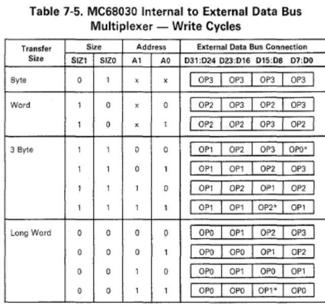
This chart from the 68030 manual shows what data will be output for any given write cycle. I went through my memory test one write at a time, writing down what would be present on the data bus and where for each cycle.
The random, nonsensical data read back from RAM immediately made sense. Where a byte write cycle should have written data to the lowest-order bits, the highest-order bits were getting saved, and vice versa.
My chip RAM chip select signals are indeed working — they’re just wired backwards.
Thankfully, that’s an easy fix. I used a CPLD for all the glue logic on this project, so all I really need to do is update the pin assignments for those four signals. I don’t even need a new board.
I might take this opportunity to further update the CPLD. I initially built out the logic for this project entirely in Quartus schematic view. I think I could do the same in System Verilog now. I suspect my old CPLD configuration may be partially responsible for my speed problems, so it may do some good to rewrite it.
Returning to 68030
It’s been two years now since I started my first foray into wire-wrap prototyping. My 68030 build, the state-of-my-art from 2019 has spent most of the last two years sitting in a box.
I had gotten it running BASIC at a quarter of the speed I had hoped for, and if the wind blew just right sometimes I could even get it to use the 68882 for maths. It worked, but only just. Too unstable for any further work. I had big plans for it, but could not continue without addressing its problems.
Well, finally, I have new progress. I ordered a PCB of the main board — exactly as it was laid out for the wire-wrap prototype.


My hope is that a proper board will help with the noise issues I was having with the wire-wrap board.
A couple hours soldering, and it was ready to move all the parts over from the prototype. Since it was made from the same schematic, and was indeed the same file I referenced for wiring the prototype, it should be that easy.
Fingers crossed it works at least as well as the prototype.

Only one way to find out …