#motorola


 - Gwen Stefani")
Full Speed Ahead … Finally
I have been building my 68030 computer around a 25MHz-rated part, so that has always been my target. My original wire-wrap prototype initially ran at half that, but as I continued to expand the project, the best I could manage was 6MHz. Eventually, the whole thing got so unstable I had to abandon plans to continue adding FPU, DRAM, IDE, etc.
I do still want to add those parts to the project, to learn more about working with them. That’s why I ordered the custom PCBs — I was hoping a PCB would be a more stable platform for future expansion and allow me to finally run the machine at the 25MHz target.
Once I got the new PCB prototype working I tried again with a 25MHz oscillator (my new glue logic no longer divides the clock like my original).
It didn’t work.
In fact, at 25MHz it failed in the same way it always had on the old wire-wrap prototype. It seemed 12 MHz was my limit.
Or was it? Maybe I just had a bad oscillator. Perhaps a new one would work better?
A ridiculous line of thought, given that the 25MHz oscillator I had did indeed run the computer at one time. But, I did want to see how fast I could get it to run, and there are some respectable speeds between 12MHz and 25MHz. So I placed an order for a few oscillators, 16MHz, 20MHz, 24MHz … I also stocked up on some common resistors and capacitors to make the most of the shipping fee.
Got the new parts in, threw on the 24MHz oscillator and … nothing. It didn’t work.
There is a problem I noticed when I did my original troubleshooting on this PCB — some of the wired-or signals had very slow rise times. I don’t have a proper oscilloscope, so it’s hard to tell sometimes if analog problems like that are measurement error or induced by stray capacitance of the measurement leads. But, the 8kΩ resistor networks I had gotten from surplus to use as pull-ups on this project were a bit high. Perhaps a lower-value pull-up resistor might help here.
Among the resistors I ordered were some 4.7kΩ and 1kΩ resistor networks. 4k7 is a fairly standard pull-up value, and some rough math had shown 1k might be a good value for this project. So I swapped out the 8k resistor networks for the new 1k networks and gave it a shot. It still ran without issue at 12MHz…
And at 16MHz.
And at 20MHz.
And at 24MHz.
And at 25MHz.
And at 32MHz.
And at 40MHz.
My MC68030 rated for 25MHz was running BASIC stable at a 60% overclock. Even the RAM was overclocked at this point, with cycles reduced to 50ns for SRAM rated for 55ns. It would seem that all this time my choice of pull-up resistor value had as much or more to do with my speed limits as the method of prototyping.
It wasn’t perfect though, and as soon as I added my SE-VGA card back into the mix it would no longer successfully load BASIC at 40MHz. It did however run just fine at 32MHz, even with the SE-VGA card.
Ludicrous Speed
In the years since I started this project I acquired another 68030 CPU — a 40MHz-rated 68EC030 (the EC units lacking the on-board MMU). I’m sure you can see where this is going.
First, I needed to modify my glue logic. RAM access cycles were going to need another wait state, ROM another two. While I was at it, I created a new cycle specifically for my SE-VGA card, with three wait states. Since my UART (68B50) is actually rated for 2MHz, and my timing was originally factored for 1MHz with a 25MHz base clock, I left the UART timing alone to push it closer to its rated speed. All-around, the new timing should support up to 50MHz base clock.
New logic, everything ran fine at 32MHz. Swapped in the EC030 and no problems. Time to see how fast it will go.
40MHz, no sweat
50MHz, still running cool
56MHz, no problems
I’m out of oscillators. My 68030 homebrew, with a 40MHz-rated EC030 is running reliably at 56MHz, a 40% overclock. Even the SE-VGA card is working, and much happier with its custom timing added to the glue logic.
I’ve been using a simple Mandelbrot rendering BASIC program as a benchmark. On my original 6MHz 68000 build, this program takes around 9 minutes to complete. When I first ran it on the 68030, running at 12MHz, with cache disabled, and BASIC in 8-bit ROM, it took just under 5 minutes. Now, with BASIC running from RAM on the 32-bit bus, L1 cache enabled, and CPU at 56MHz, the Mandelbrot program completes in 14 seconds. That is an incredible performance increase for a simple homebrew computer.
It does generate some heat now, so I added a small heatsink to the CPU to be safe. Current consumption for the system is up 300mA just from raising the clock speed.
Motorola originally sold 68030 CPUs rated as high as 50MHz. I wonder if my later production units just benefit from what they learned pushing the architecture that high, or if it’s reflective of what the CPU can handle in general. Could I push a 50MHz part up 40%? A 70MHz 68030 homebrew certainly would be interesting.
Serial Expansion
TSMON, the ROM monitor I’m running on my 68030 board, is designed to use two serial ports — one for the primary console, and one for an attached development computer. I’ve only ever used it with a single serial port. It would be useful to have a second for loading programs straight into memory. My 68030 board only has a single UART footprint, but why should that stop me?


I built a breakout board that plugs into the socket for the existing UART and adds a second. It holds a pair of 6850 UARTs, a 74'139 for address decoding, and a MAX232 level shifter. I even added some jumpers to disable the second UART if necessary.
It worked without issue with just the first UART populated, and the second UART did not interfere with the first one when it was added.

I’ve updated TSMON to add back in code for the second serial port which I had previously removed. I also edited the EhBASIC VEC_IN routine to check both serial ports for data. Now I can send BASIC programs over serial from another computer then run them using a terminal connected to the first serial port on the 68030 board.
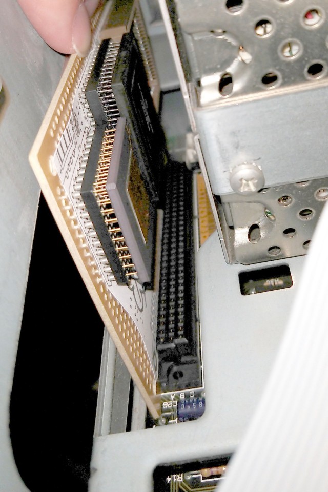
Returning to 68030 … Again
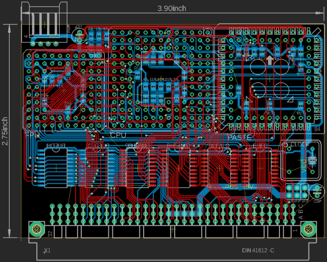
I left off with my 68030 homebrew project having just finished assembling a new PCB that was 1:1 with my wire-wrap prototype.

It did not work.
In theory, it should have been as simple as transferring all the chips from the prototype to the PCB and starting it up. Reality is never so friendly as that.
It was failing in a familiar fashion, with errors coming swiftly after startup. It reminded me of a big problem I’d had with at the beginning, before I had properly implemented the chip select signals for RAM. But I had solved that problem a long time ago, how could it be back?
Turns out I had the chip select signals for RAM routed backwards. The RAM chip for the high 8 bits of the data bus was getting the enable signal for the low 8 bits, and so on.
I dug out the glue logic, changed those four pin assignments, and burned a new CPLD and … nothing. Nothing worked. It was worse than I started and now it wouldn’t even run when I reassembled the prototype.
Back in the box it went, for months.
I finally pulled it out recently and set out to get it running, starting with all new glue logic.
The original logic was all done in the Quartus schematic builder. At the time, it was too complex for my rudimentary VHDL skills. I’ve been learning Verilog and have built some successful projects with it that are far more complicated than this glue logic. So I started from scratch, rewrote all the logic fully synchronous in Verilog.
I started testing as small and basic as I could, stepping through each piece to confirm it worked before moving on. The logic responded appropriately to signals toggled manually. The CPU was able to free run with its data bus held low and the glue logic providing the termination signals. It was able to run code from ROM.


There were of course a few odd bugs here and there in the new glue logic, but in all it progressed fairly smoothly. I started writing some test programs to test the bus and make sure I got the chip select signals right this time.

With no RAM actually connected, it failed every test just as expected. Finally, it was time to add in the RAM.

RAM tests passed. I had a working computer again! Time to dust off the source code for the TSMON monitor program and Enhanced BASIC.
TSMON loaded and ran with few problems. Similar to my 68000 build, I wrote an expansion ROM for TSMON to load BASIC from ROM into RAM before running it.

So now I’m back where I was a couple years ago — I have a homebrew 68030 running BASIC.
This time though, it’s running fairly stable at 12MHz. The old wire-wrap prototype struggled to run stable at 6MHz.
 ALT
ALTBuilding a Faster SE
The Macintosh SE was the first Mac model to support internal expansion cards, by way of its Processor Direct Slot. As the name implies, the PDS connector exposes most of the 68000 processor signals. This makes it an ideal candidate for a CPU upgrade card. Many such products were available in the early 1990s, offering faster and newer processors, cache, additional memory etc.
The Motorola 68030 is a great option for accelerating an existing 68k system. It has the same instruction set, with a few additions, so all the same code will run. It also supports dynamic bus sizing, so it can easily interface with 8-, 16-, and 32-bit peripherals. And it supported clock speeds up to 50MHz. All around, it’s a fairly easy 32-bit processor to start with, and it can be adapted to the 68000 bus with minimal additional logic.
 ALT
ALTSo I tried my hand at making a 68030 accelerator card for the Mac SE. It has a 68030 CPU & 68882 FPU, and uses an Atmel ATF1504 CPLD & some 74'245 buffers as glue logic adapting the 32-bit bus of the 68030 to the 16-bit bus of the 68000 and SE.
I’ve not added any cache or extra RAM. I thought it best to start small and get the basic bus translation working first. Ideally, this little card would be transparent to the OS, perhaps only needing a small init to enable the 68030 L1 cache or announce presence of the FPU.
If I can get this basic card to work, I might move on to adding L2 cache or 32-bit-wide RAM to help further accelerate the system.
That bold gold yellow on black & chrome")
That bold gold yellow on black & chrome")
That bold gold yellow on black & chrome")
Motorola 3BMXB1 // Tone Pager for British Telecom (1980)
That bold gold yellow on black & chrome yummy yum yum
Post link

Amanecer Ranchero.
Amanecer del 15 de Junio en Guadalajara.
Foto: Enrique Jiménez

.")
.")

Папика осеменило.
https://vk.com/page-29534144_48664258
Внемли голосу яндекса.
http://siliconrus.com/2014/10/diktovka/
YAC2014: Browser для Linux.
http://browser.yandex.ru/beta/
Наиболее интересный из фитнесс-трекеров.
http://geektimes.ru/company/medgadgets/blog/240821/
Lenovorola.ru.
http://4pda.ru/2014/10/31/183609/
http://siliconrus.com/2014/10/motorola/
Цнн не может сюрфейс.
http://tjournal.ru/paper/cnn-surface-ipad
Медуза — ПЦ.
https://meduza.io/news/2014/11/13/zayats-pts-nu-i-valite-v-svoy
Киборги заполоняют.
http://www.3dnews.ru/904606/
Inbox? По секрету тут напишу — у нас есть инвайты. Пишите.
https://inbox.google.com/
Жоля докатилась.
http://www.3dnews.ru/904946/
The Motorola 68000 Processor from a Commodore Amiga 500 home computer
medium-sized banana for scale


Pixelart concept & Makeup for ELLE Romania x Motorola
Photography / Christian Tudose
Styling / Maurice Munteanu
Hair / Raluca Crăciun
Model / Maria
Post link

From my new phone.
My new wallpaper of my wife Jane Lane-Grambow.


Google-owned Motorola Mobility announced a new hardware project today called Ara.
Ara is to phone hardware what Android was to phone software. It offers a toolkit for manufacturers to create fully customizable smartphones. And these toolkits will supposedly be plug-and-play.
Asthis article on TheNextWeb says beautifully:
You start with a bare-bones creation made up of a base board and add on the components you really need, and then those you really want. Don’t use a camera on your phone? Simpy (sic) swap out the camera module and put in more storage. Is the processor positively sluggish for your use? Easy, just swap in a newer one with a higher clock speed.
Now, I think there’s a lot to be said here for the project. When it comes to either purchasing a pre-manufactured desktop versus building your own, both power and affordability are optimized in the DIY market.
However, self-built PCs struggle from an achilles heel – you have to know how to build them. Regardless of how easy some claim it is, the average person doesn’t want to risk breaking their new >$1000 investment because they were trying to but the square peg into the round hole.
So I’d say this: the major challenge that Motorola’s Ara will face is making it easy to self-manufacture.
Perhaps this can be done by making the modules extremely resistant to breaking, or making the process of putting them together more akin to building something out of legos rather than putting together an IKEA desk.
No matter what, I’d highly doubt that folks who currently shell out $199 for an iPhone for few reasons other than its meticulous, beautiful design, will switch to the self-built phone any time soon. Certainly there is a market for it, but until the form factor goes away altogether, there will be customers on the massive-scale manufacturing scene.
However
This actually could be a red herring. With the recent developments in 3D printing that we’re beginning to see, one might wonder if the manufacturing industry as a whole is beginning to wane. It’s certainly an exciting view of the future to have a device, sitting in your home, from which you can make any assortment of things that you’d otherwise buy from a store.
Perhaps Ara is one step towards this universal self-manufacturing vision. Perhaps Ara will prove, once and for all, that design can be built in to a self-built machine, and that folks won’t care that they have to do an extra hour of work to get there.
I’m not certain, but regardless, Ara has a long battle ahead of it to prove itself.


