I have an old Mac Plus that was given to me nearly 25 years ago. For as long as I’ve had it, it has not been a functional computer.
ALT
Over the years I’ve robbed it for parts for other projects — sometimes rather destructively. One serial port was sawed off in my early teenage years, the other was clearly desoldered much later. The serial chip was removed for my first Z80 homebrew. The 68000 CPU was used for my first 68k homebrew. The oscillator was removed for other homebrew projects. Remaining parts were marked for whether they were generic or proprietary, so I could know whether they would be useful for future projects.
Every part I’ve removed from this board has been functional. When we tested the machine 25 years ago, it did not power on or show any other signs of life. Knowing what I do now, it’s obvious to me that it had a bad analog board, but the logic board was probably still good.
I think it’s time to breathe new life into this abused machine. Luckily, I still have the parts I removed from it.
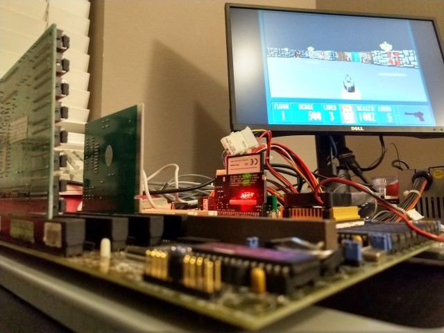
One of the goals of my SE-VGA project is to support older classic Macs that whatever reason no longer have functional CRTs. I of course had this old Plus in mind all along when designing that into the SE-VGA. As soon as I knew the Rev 2 boards were functional, I assembled one with 68000 CPU headers instead of the SE PDS connector.
ALT
Since the analog board for this Plus is bad, I’ll need some other way to interface with a monitor. The SE-VGA board will allow me to use any VGA monitor in place of the original CRT.
The analog board is also the power supply for the Plus, so I’ll need a new power supply as well.
ALTALT
I have an old XT era power supply with a similar connector to the analog connector on the Plus motherboard. It’s a standard Molex part with removable crimp-on contacts. It was fairly easy to remove all the contacts and rearrange them to match the layout required to power the Plus motherboard.
The board powered on, the SE-VGA output its video, but the Plus was not happy. Every time it powered on, it gave Sad Mac error 02FFFF. This code means it passed the ROM checksum, but it was failing the first RAM test. The FFFF on the error code would indicate that every RAM chip was bad. Since it gave the same error with or without RAM installed, and with known-good RAM installed, the problem is clearly elsewhere.
ALT
I started by probing the data path between the CPU and RAM. Data was making its way through the buffers, and as best as I could tell RAM and the DRAM control state machine were working properly. So I turned to a disassembly of the ROM to see what it was actually testing.
The first RAM test starts at address $00,0000, writes data, then reads it back. Then it moves to address $00,0001,$00,0002,$00,0004,$00,0008,$00,0010, etc. It’s not really testing the data bus here, it’s testing the address bus, looking for stuck address signals. So I started probing the address multiplexers. Every CPU address signal to the RAM was accounted for except A1.
When the 68000 CPU was removed from this board, the pad for A1 was damaged. A hairline crack separated the pad from its trace. A quick bodge wire, and no more Sad Mac.
The next problem I encountered was an interesting one. The insert disk icon — a floppy disk with a blinking question mark — wasn’t blinking. This time, The Dead Mac Scrolls held the answer: early Macs without a floppy drive connected won’t blink the question mark.
So I pulled an 800k floppy drive from my SE and plugged it in. On power up, the eject motor spun up … and continued spinning.
[Sark] had the answer for this one. There are a few different versions of floppy drives Apple used. They are compatible, but using newer drives in older computers sometimes requires a specific cable (the yellow stripe cable) which cuts pins 9 & 20. One custom cable later, no more constantly-running eject motor, and the question mark blinks as expected.
I don’t currently have any 800k bootable floppy disks, so I ordered a new BlueSCSI. The latest BlueSCSI revision supports the Mac Plus, and indeed booted right up without issue.
But once booted, the mouse didn’t work. It would only move vertically, not horizontally. Logic analyzer showed the mouse was properly outputting quadrature signals from the rotary encoders, but the computer wasn’t responding to them. Back to the schematics, tracing the signals and sure enough, another broken trace and another bodge wire.
ALTALT
Finally, there was only one thing left to do — build a keyboard cable. The early Macs used a cable that looks like the handset cable on an old analog telephone, but the keyboard cables were wired straight through instead of crossed like the phone cables. I had to order the proper terminations and tool, but had no problems assembling it.
It was a lot of work, and required pulling together many different parts and pieces, but finally this old Mac Plus lives again.
I’ve been working on the new revision of my SE-VGA project I mentioned previously.
ALTALT
These new boards use nearly all surface-mount parts, instead of the through-hole parts used on the first boards. The biggest functional change is the can oscillator has been replaced with a 13MHz crystal and a selectable clock multiplier — this allows a 65MHz pixel clock for running 1024x768@60 resolution (XGA) instead of the 640x480@60 (VGA) from the first boards. The Mac 512x342 resolution can be pixel doubled to fit into an XGA frame, with small black boarders (letterboxing) top and bottom.
I’ve rewritten the logic from scratch. The original logic was overly-complicated and I wasn’t able to adapt it to the new resolution. Of course they means a whole lot of debugging, and brings to fore a problem with moving to small surface-mount components — no place to attach test leads.
ALT
I soldered some 30ga wire-wrap wire to key signals (in this case the VRAM control signals) so I could watch them with a logic analyzer for debugging. These pins are quite small, no larger than the wire itself. Soldering to them was finicky and took a few attempts. I taped the wires down to prevent them from pulling out while working.
ALT
Another big difference with these new boards is they support not just the Mac SE, but also older 68000 Macs as well. Here I’ve assembled one for a Mac Plus and I’m testing its fit around other components on the Mac Plus motherboard.
The logic is coming along well. I’ve encountered many of the same problems I had with writing the VGA logic and had to solve them all over again. At this point it does show the whole frame of video, but I have some random glitches with VRAM writes, and some of my timing is a little off. It is working as a proof of concept though. I should be able to clean up the logic and get it running smoothly.
This project has some interesting firsts for me. It’s the first project I’ve ever designed a second revision and ordered a second round of boards for. It’s also the first project I’ve ever made more than one of. Depending on how things go I might actually do a third board revision to clean up anything I find not working reliably.
The first computer I spent any significant amount of time on was the predecessor to this, the Sanyo MBC-1000.
It was a 1982 model that ran CP/M on a 4MHz Z80. It had a wonderful green phosphor display, and you could edit the character maps to display custom glyphs (it had no other graphics capabilities).
We had the dual disk drive expansion and a dot matrix printer to go with it. Not much software outside of the Star office suite, but it did have BASIC. I spent a lot of time exploring BASIC on that old machine before I really knew what I was doing.
We got it second-hand around 1998, and replaced it in 1999 with a Macintosh Classic from 1990. The next year we finally caught up to the times and bought a new eMachines (“Never Obsolete!”) desktop. In just two years, I crossed some twenty years of computing history.
Somehow it feels like so much longer than that. Perhaps it’s because of how much I was able to learn so quickly.
I may have gotten a late start, but it laid the foundation for a passion and productive hobby working with older computers, and set me up for a career in IT.
I don’t have any pictures of the MBC-1000, but Old Computer Museum has a great one.
(oh that keyboard was lovely. I wish I could have caps like those again.)
Inspired by recent work on creating modern reproductions of the Mac SE logic board and following my previous CPLD VGA generator project, I’ve been working on a PDS card for the Mac SE that mirrors its video on a VGA monitor.
I’m using a similar approach to the [bbraun] project, which used an stm32f4 to watch the SE’s CPU bus for writes to the SE frame buffer memory addresses. Instead of using a microcontroller I’m using an Atmel ATF1508AS CPLD to monitor the SE CPU bus for writes to the frame buffer addresses and storing the data in a pair of 32kB SRAM chips. The CPLD then reads back the video data to generate a 640x480 monochrome VGA signal with the SE video in letterboxed in its original 512x342 resolution.
The circuit itself is fairly straightforward. The CPLD runs everything off a single clock signal from a can oscillator, and uses the pair of SRAM chips for video memory. Other than those four chips, there are a few passive components. It’s simple enough I could have built one with point-to-point wiring or even wire-wrap. But, to reduce debugging and the potential for noise disrupting the SE’s normal operation, I decided to lay out and order some small PCBs.
I got these from JLC for $2 plus shipping and they arrived in just under two weeks. Build was easy enough. I used the drag solder technique with a lot of flux to solder on the 100 pin QFP package CPLD and it went on with no problems. Everything else is through-hole.
I tried to take a methodical approach to build and debug. I started with just the CPLD and clock to make sure it could generate a proper sync signal that was recognized by my monitor. That much worked without issue, so I moved on to testing if it could read data from its VRAM bus and display it. This part took some work with a logic analyzer and a few rounds of updates, but eventually I was able to tie one VRAM Data pin high and get it to display lines.
From there, I added the VRAM sockets to test if it could properly read from VRAM and display its contents. SRAM powers on to random contents, and when I added the SRAM to the board and powered it on, I was greeted with a screen of random pixels. VRAM was working, and the video generator was displaying a stable, consistent image.
At this point there was only one thing left to do — solder on the (expensive!) DIN 41612 connector and test it out in the SE.
Well, it was half working.
I had half of the image on screen, so it was clearly recognizing CPU write cycles, storing it in VRAM, and recalling it in sequence. I quickly found and corrected a bug in the code looking for the 68000 lower data strobe (!LDS), and inverted the final output and tried again.
It … Wasn’t quite right. It started out fine while Mac OS was booting. There was a little noise in the image, but not too bad … until it reached the Finder. By the time it was finished booting, it was flashing, alternating between valid video data and a garbage data. The garbage data seemed to be encroaching on the valid data as well, the longer the system ran.
The first bug didn’t take long to find. The classic Macs, including the SE actually support double-buffered video. They have a primary frame buffer and an alternate frame buffer, selected by setting or clearing one output bit on the VIA chip. I designed the card to support both frame buffers, and to also watch the CPU bus for writes to the specific VIA bit that controls frame buffer selection. I had calculated the VIA address wrong though, so it was swapping between frame buffers when it shouldn’t have and that’s what was causing the flashing.
I still had the problem of garbage data being displayed however. This one took a while to figure out, and I’m actually still not sure how it was happening to begin with.
The logic analyzer showed that every so often a VRAM write cycle would overlap with a VRAM read cycle. The VRAM write state machine shouldn’t have allowed that to happen, but it was. Unable to find anything that would cause the cycles to overlap, o added a test to delay the write cycle if it detected a current read cycle.
The result?
No more garbage data.
I really can’t believe it. I wasn’t sure I could get this to work, and I wasn’t sure it would fit into a CPLD with only 128 macrocells. To top it off, this is my first real project using System Verilog instead of VHDL.
It’s not perfect yet. There is one column of garbage data being displayed on the left of the image, and it looks like the last column off the right is also ending up on the left. But, it is completely useable.
I’m not finished with this project yet. I want to bump it up to XGA resolution (1024x768), which would allow the SE video to be pixel doubled and take up more of the screen. The 65MHz clock necessary for XGA is hard to come by, so I’m thinking about spinning up a rev 2 board that uses an FPGA instead of a small CPLD.
This has been a fun project. It’s always so exciting for a project to have visible results.
I have the project on GitHub if anyone is interested in taking a closer look.
Rev 2
I’ve been working on laying out a Rev 2 board. It’s proven to be quite a bit more challenging than the first.
I had a few goals for the second revision:
Fix a few bugs from the first board
Change resolution to 1024x768
Add support for more than just SE PDS
The first was minor, mostly just cleaning up some poor design decisions around the output voltage shifter.
The second is something I mentioned already as on my to-do list. Instead of displaying the Mac 512x342 image surrounded by a black box in a 640x480 frame, it would be better to pixel-double the image to 1024x684 and display it letterboxed in a 1024x768 frame. This requires a 65MHz clock, which is not that common for can oscillators. After some digging around, I’ve decided to use a common 13MHz crystal with a configurable clock multiplier set to 5x for the 65MHz pixel clock.
The last change was a suggestion from [Kai Robinson] — add a footprint for the 68000 CPU so the board could be inserted in place of the CPU, leaving the SE PDS slot free for an accelerator. This has the added bonus of making the board compatible with the Plus and 512k models as well.
The first two changes were easy. That last one though has been a challenge. The 68000 signals are reversed from the layout of the PDS slot. Every signal had to cross itself. In addition, on the Plus, there is no room beyond the CPU without running into the tops of the RAM SIMMs. I tried putting the PDS connector on one end and the 68000 footprints on the other, but never could get all of the signals past the CPLD without adding layers. I completely started over on routing this board half a dozen times.
Finally, I came up with this layout that puts the PDS connector between the 68000 footprint for the board, and a socket footprint to hold the 68000. The right-angle DIN 41612 connector needs a little space where the board rests against the back edge of the connector for stability; the bottom pins for the 68000 board connector fit into this space.
While I was working on it, I also changed to surface-mount SRAM chips. Not only are these parts cheaper than, DIP, they’re much lower-profile. That would allow this board to be used with a straight DIN 41612 connector in early SE units that don’t support vertical PDS cards. In this arrangement, the board would be installed component-side down towards the SE motherboard, so thinner is better.
I’ve spent the last couple days just cleaning up the ground pours and silkscreen layers. I think I’ve done all I can at this point, time to place the order. The last boards just took a couple weeks to arrive. As of right now, the CPLD is back-ordered for … a couple weeks. Perhaps if I order now they’ll all come in around the same time.
In the meantime, the CPLD configuration will need significant rework to support the new output resolution.
I ordered some boards for my Mac SE accelerator. I’m quite pleased with how they look.
ALTALT
Assembly wasn’t too bad. The 0805-size resistors and capacitors can be a bit fiddly to work by hand, but they’re still manageable. In all, it just took a couple hours to put together the first test board.
ALT
It fits in my SE with plenty of clearance between it and the floppy drive cages.
So the big question is — does it work?
ALT
Of course not! What fun would that be?
First run attempt was just a garbled screen, and not even the infamous checkerboard pattern. I didn’t expect it to be fully functional at first attempt, but that pattern is a new one.
Time for the logic analyzer.
I can see the hand-off working. The accelerator asserts the Bus Request signal to take the SE 68000 off the bus, and waits for the Bus Grant signal in response. Once the 68000 is off the bus, the 68030 is brought out of reset and allowed to take over. That much worked as expected.
Next thing to look at is whether the 68030 is starting up properly. The first thing it’s going to do is load the initial startup vector and stack pointer from ROM. These are 32-bit values, so each will take two access cycles over the 16-bit SE bus. It was getting stuck on these initial read cycles, waiting for a bus termination signal
The 68k processor family has a great asynchronous bus that relies on peripherals providing an appropriate bus cycle termination signal. Macintosh computers generate the termination signal synchronous to the system clock. What I found was the faster 68030 (running at 12MHz for testing) was sometimes ending one cycle and starting the next within a single clock pulse of the main 8MHz SE clock. The SE motherboard logic never saw the new CPU cycle begin.
My first draft of logic was largely asynchronous, and paid little attention to the system clock. But since the SE motherboard logic is synchronous and expecting 68000 bus cycles, I need my logic to better emulate 68000 bus cycles.
So I rewrote nearly all of the logic for the CPLD to roughly emulate 68000 bus cycles.
ALT
Never thought I’d be happy to see a Sad Mac error. That error means the 68030 is running enough code for the initial ROM checksum to fail. That’s quite an improvement over not even loading the initial vectors.
I’ve got a long way to go on this project, but it’s looking promising. Running any code at all is a great sign. I can already see a the next few logic bugs that need to be addressed, and I’ve found a few hardware bugs that’ll need bodge wires.
The Macintosh SE was the first Mac model to support internal expansion cards, by way of its Processor Direct Slot. As the name implies, the PDS connector exposes most of the 68000 processor signals. This makes it an ideal candidate for a CPU upgrade card. Many such products were available in the early 1990s, offering faster and newer processors, cache, additional memory etc.
The Motorola 68030 is a great option for accelerating an existing 68k system. It has the same instruction set, with a few additions, so all the same code will run. It also supports dynamic bus sizing, so it can easily interface with 8-, 16-, and 32-bit peripherals. And it supported clock speeds up to 50MHz. All around, it’s a fairly easy 32-bit processor to start with, and it can be adapted to the 68000 bus with minimal additional logic.
ALT
So I tried my hand at making a 68030 accelerator card for the Mac SE. It has a 68030 CPU & 68882 FPU, and uses an Atmel ATF1504 CPLD & some 74'245 buffers as glue logic adapting the 32-bit bus of the 68030 to the 16-bit bus of the 68000 and SE.
I’ve not added any cache or extra RAM. I thought it best to start small and get the basic bus translation working first. Ideally, this little card would be transparent to the OS, perhaps only needing a small init to enable the 68030 L1 cache or announce presence of the FPU.
If I can get this basic card to work, I might move on to adding L2 cache or 32-bit-wide RAM to help further accelerate the system.
I had dared to hope that since this board was created from the same schematic and board file I had made and referenced for my wire-wrap 68030 project, that I could just move the parts over and let it run. If I was really lucky, it might even be able to run faster than the original.
I should know by now it’s never that easy.
The board does indeed run. It starts up, initializes its serial port, copies BASIC into RAM, verifies the copy, then starts running BASIC. It never gets to the BASIC ready prompt though.
Time to pull out the logic analyzer. This would certainly be easier if I had a proper logic analyzer with 64 or even over 100 channels, but there is a lot that can be learned 16 channels at a time. Watching important parts of the address bus I was able to watch it step through the BASIC initialization routines. However just before it got to the point where it would print its first carriage return, it jumped to an address I didn’t expect, and I couldn’t follow where it had gone. Shortly after, it would start accessing invalid addresses and generating bus errors.
The point where I lost it was right when it called a vector to its character print subroutine. This version of BASIC is written to be position-independent, so it has a short vector table for common I/O handlers in its global variable space. When it’s time to call one of these routines, it performs a jump operation using the vector in that table ( jsr voutp(a3)).
I could see it getting that far, recall the vector, and push its return address to stack. But where it ended up was a mystery.
This points to memory corruption somewhere, but where? I had a similar issue when I was building the prototype, before I had properly built out the RAM chip select signals, but that fix is already incorporated into this board.
I started writing some memory test routines. Unsurprisingly, long word write and read back tests all passed (after all it was loading and verifying BASIC the same way already). Byte-level tests also passed without issue. I needed something more thorough.
I put together a simple test that would write a single byte, followed by writing a long word, alternating for 16 total bytes. This would force it to write misaligned long words to confirm RAM addressing was working correctly.
It failed.
The bytes read back were all jumbled, and a couple values were missing altogether. This really was looking like that old problem with the missing chip select signals, but I had already verified those were firing.
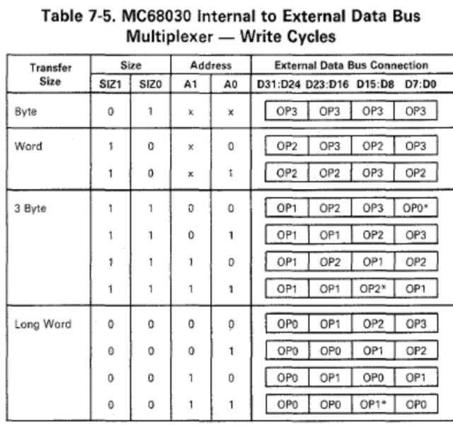
This chart from the 68030 manual shows what data will be output for any given write cycle. I went through my memory test one write at a time, writing down what would be present on the data bus and where for each cycle.
The random, nonsensical data read back from RAM immediately made sense. Where a byte write cycle should have written data to the lowest-order bits, the highest-order bits were getting saved, and vice versa.
My chip RAM chip select signals are indeed working — they’re just wired backwards.
Thankfully, that’s an easy fix. I used a CPLD for all the glue logic on this project, so all I really need to do is update the pin assignments for those four signals. I don’t even need a new board.
I might take this opportunity to further update the CPLD. I initially built out the logic for this project entirely in Quartus schematic view. I think I could do the same in System Verilog now. I suspect my old CPLD configuration may be partially responsible for my speed problems, so it may do some good to rewrite it.
It’s been two years now since I started my first foray into wire-wrap prototyping. My 68030 build, the state-of-my-art from 2019 has spent most of the last two years sitting in a box.
I had gotten it running BASIC at a quarter of the speed I had hoped for, and if the wind blew just right sometimes I could even get it to use the 68882 for maths. It worked, but only just. Too unstable for any further work. I had big plans for it, but could not continue without addressing its problems.
Well, finally, I have new progress. I ordered a PCB of the main board — exactly as it was laid out for the wire-wrap prototype.
My hope is that a proper board will help with the noise issues I was having with the wire-wrap board.
A couple hours soldering, and it was ready to move all the parts over from the prototype. Since it was made from the same schematic, and was indeed the same file I referenced for wiring the prototype, it should be that easy.
Fingers crossed it works at least as well as the prototype.
Inspired by recent work on creating modern reproductions of the Mac SE logic board and following my previous CPLD VGA generator project, I’ve been working on a PDS card for the Mac SE that mirrors its video on a VGA monitor.
I’m using a similar approach to the [bbraun] project, which used an stm32f4 to watch the SE’s CPU bus for writes to the SE frame buffer memory addresses. Instead of using a microcontroller I’m using an Atmel ATF1508AS CPLD to monitor the SE CPU bus for writes to the frame buffer addresses and storing the data in a pair of 32kB SRAM chips. The CPLD then reads back the video data to generate a 640x480 monochrome VGA signal with the SE video in letterboxed in its original 512x342 resolution.
The circuit itself is fairly straightforward. The CPLD runs everything off a single clock signal from a can oscillator, and uses the pair of SRAM chips for video memory. Other than those four chips, there are a few passive components. It’s simple enough I could have built one with point-to-point wiring or even wire-wrap. But, to reduce debugging and the potential for noise disrupting the SE’s normal operation, I decided to lay out and order some small PCBs.
I got these from JLC for $2 plus shipping and they arrived in just under two weeks. Build was easy enough. I used the drag solder technique with a lot of flux to solder on the 100 pin QFP package CPLD and it went on with no problems. Everything else is through-hole.
I tried to take a methodical approach to build and debug. I started with just the CPLD and clock to make sure it could generate a proper sync signal that was recognized by my monitor. That much worked without issue, so I moved on to testing if it could read data from its VRAM bus and display it. This part took some work with a logic analyzer and a few rounds of updates, but eventually I was able to tie one VRAM Data pin high and get it to display lines.
From there, I added the VRAM sockets to test if it could properly read from VRAM and display its contents. SRAM powers on to random contents, and when I added the SRAM to the board and powered it on, I was greeted with a screen of random pixels. VRAM was working, and the video generator was displaying a stable, consistent image.
At this point there was only one thing left to do — solder on the (expensive!) DIN 41612 connector and test it out in the SE.
Well, it was half working.
I had half of the image on screen, so it was clearly recognizing CPU write cycles, storing it in VRAM, and recalling it in sequence. I quickly found and corrected a bug in the code looking for the 68000 lower data strobe (!LDS), and inverted the final output and tried again.
It … Wasn’t quite right. It started out fine while Mac OS was booting. There was a little noise in the image, but not too bad … until it reached the Finder. By the time it was finished booting, it was flashing, alternating between valid video data and a garbage data. The garbage data seemed to be encroaching on the valid data as well, the longer the system ran.
The first bug didn’t take long to find. The classic Macs, including the SE actually support double-buffered video. They have a primary frame buffer and an alternate frame buffer, selected by setting or clearing one output bit on the VIA chip. I designed the card to support both frame buffers, and to also watch the CPU bus for writes to the specific VIA bit that controls frame buffer selection. I had calculated the VIA address wrong though, so it was swapping between frame buffers when it shouldn’t have and that’s what was causing the flashing.
I still had the problem of garbage data being displayed however. This one took a while to figure out, and I’m actually still not sure how it was happening to begin with.
The logic analyzer showed that every so often a VRAM write cycle would overlap with a VRAM read cycle. The VRAM write state machine shouldn’t have allowed that to happen, but it was. Unable to find anything that would cause the cycles to overlap, o added a test to delay the write cycle if it detected a current read cycle.
The result?
No more garbage data.
I really can’t believe it. I wasn’t sure I could get this to work, and I wasn’t sure it would fit into a CPLD with only 128 macrocells. To top it off, this is my first real project using System Verilog instead of VHDL.
It’s not perfect yet. There is one column of garbage data being displayed on the left of the image, and it looks like the last column off the right is also ending up on the left. But, it is completely useable.
I’m not finished with this project yet. I want to bump it up to XGA resolution (1024x768), which would allow the SE video to be pixel doubled and take up more of the screen. The 65MHz clock necessary for XGA is hard to come by, so I’m thinking about spinning up a rev 2 board that uses an FPGA instead of a small CPLD.
This has been a fun project. It’s always so exciting for a project to have visible results.
I have the project on GitHub if anyone is interested in taking a closer look.
A couple years ago now, I cleaned up my old IIcx motherboard. It had some significant corrosion from leaking capacitors. There were a couple traces I found that had been eaten through, and in the case of R3 to C2, a via was completely gone.
I added bodge wires to fix the breaks I had found, and the machine booted and ran just fine. There was just one lingering problem — the internal speaker was mute.
The sound circuits were working. With headphones in, I could successfully test both stereo channels. But no matter what I did I couldn’t get the internal speaker working.
I had hoped my bodge wires would fix it. I thought maybe it was dirty contacts inside the headphone jack. Nothing helped.
I finally sat down recently with a copy of the Bomarc schematics and found the issue.
See, unlike every other device I’ve encountered before, the headphone jack for the IIcx has a DPDT switch. Most devices have an SPST switch to detect when headphones are plugged in. The IIcx though uses one switch to detect when the headphones are connected, and one switch to disconnect the internal speaker.
Following the schematic, I had continuity from the speaker all the way across the motherboard (in an internal layer) to the headphone jack. On the other side of the headphone jack though, continuity was broken. What I could see of the trace was fine. My best guess is it is broken underneath the ADB filter where I can’t see it.
ALT
I ran a new bodge wire — from the headphone jack to the other side of R3 — and now continuity is good all the way from the sound chip through the headphone jack, and to the internal speaker.
I was given a 1993 500MB LaCie external SCSI hard drive along with my (1990) Mac IIcx. When the original Quantum 80MB hard drive from the IIcx failed, I pulled the Seagate 500MB drive out of the case and installed it in the IIcx.
It lasted nearly 20 years in the IIcx.
It survived nearly a decade in non-climate-controlled storage in East Texas heat & humidity.
Now, it suffers from [integer overflow] bad sectors.
Thankfully, I was able to get a complete dd image of the disk in 2019 when I got this machine working again (and acquired a Beige G3 which supported SCSI disks and OSX). There was some corruption and a few files and apps were unreadable, but the image is largely complete.
Farewell little 500MB Seagate drive. At 28 years old you far exceeded anyone’s expectations.
Here we see a hack I did more than fifteen years ago, when I lacked much of the knowledge, experience, and materials I have at my disposal now. I overclocked my PowerMac G4 Sawtooth. Stock it ran at 450MHz; I was able to get it to run stable at 500MHz.
The CPU card for these old G4s used a few resistors to set the bus multiplier. For this old Sawtooth model, it was R7, R9, R11, R13.
I removed the resistors that were there originally and soldered some enameled magnet wire in their place. On the other end, I soldered a set of DIP switches to allow me to experiment with the multiplier without a lot of effort. I only had this bank of six switches, so two are unused. And then, lacking anything better, I wrapped it in tons of electrical tape.
I tried setting the multiplier up to 5.5x to get it up to 550MHz, but it wasn’t stable enough to boot. At 600MHz it wouldn’t even power on. I believe it could be set down to 3.5 or 3.0, should I ever have any reason to underclock the machine.
I used this computer, overclocked to 500MHz and running MacOS 10.5 for years before passing it on to a family member who used it for several more years. Never once had an issue with the overclock or my crude hack.
In the 15 years since, the tape has obviously collected a lot of dust, but the computer still runs fine. I’m just a extra cautious when it comes to working around those fine wires.
Every one of these boards had a timebomb attached to it from the factory. Two of them it was in a holder, one it was soldered to the motherboard. I’m talking about the battery of course (though one of these boards did have some significant damage from leaking capacitors)
Those little 3V ½AA batteries are notorious for leaking and destroying motherboards. Replacements are still available, but they’re not common and thus they are also not cheap.
Coin cell batteries, specifically the 2032 size batteries, are common and cheap. While they have been known to leak on occasion, it is a much less common occurrence than the ½AA batteries.
So, I have been working on replacing the batteries and holders in my collection with these holders for 2032 size coin cells. So far I’ve completed my Mac SE, IIcx, and PowerMac G4.
This isn’t a set-and-forget modification. The batteries do need to be inspected regularly, and replaced when they start to go flat. But I should at least get a few years of not having to reset the mouse speed & time/date every time I want to use one of these machines.
The Sony floppy drives Apple used in early Macintosh models have a common critical failure in the eject mechanism. There is one gear made from a different plastic from the others that tends to break down over time.
I don’t know what is special about this particular gear, but after 30 years it’s rare to find one without any damage. Once they start losing their teeth, the auto eject mechanism can no longer function. MacOS, which expects to be able to eject any disk at will, does not like this very much. Of course it’s also difficult to remove any disk from the drive, requiring a straightened out heavy duty paperclip.
Luckily, there is a modern solution. A few people have carefully crafted 3D models of the gear for reproduction. Some are selling individual replacements through the usual sites, but often at somewhat high prices (at least as far as my limited project budget is concerned).
Thankfully [Stephen] has created an open-source replacement, and listed it for sale on Shapeways, quantity 12 for $8. With at least four drives in my collection already needing new gears, that’s an easily affordable way to get all my drives running again, and have plenty of spares.
ALT
I’ve never ordered from Shapeways before. It took a few weeks for the parts to be printed and shipped, and they arrived in a box far larger than necessary. But, the gears arrived safely. They’re certainly not perfect — they’ve got some unevenly-spaced teeth, and they don’t appear to be completely round — but they install without issue.
ALTALT
What’s most important though is: they work. I’ve replaced three so far without issue. It does sometimes sound like the mechanism is straining a little to eject a disk. I’m not sure if this is due to the imperfections of the reproduction gears or if I just need to do a better job cleaning and relubricating the drives.
Time will tell if these new 3D printed parts will hold up or need regular replacing. Until then, I’m glad to have my drives ejecting properly again.
I have no connection to Stephen or Shapeways, and have not been compensated for this post in any way.
I picked up an old Mac SE that had a bit of a problem: terrible distortion and interference appearing as horizontal lines on the monitor. It otherwise boots without issue, so the problem is most likely on the analog board.
With these old Macs, it’s common to find capacitors have failed and leaked, often wreaking havoc on the boards in the process. This machine though was surprisingly clean. There were none of the telltale signs of leaked capacitor electrolyte on the top of the analog board. The connectors were all clean, with no sign of corrosion.
Removing the analog board, and the plastic insulator attached to it, did not immediately indicate the cause either. There did end up being one capacitor that had leaked through the back side of the board, but it was part of the -5V power supply, and was not involved with the video circuitry.
It took a magnifying glass and bright light at just the right angle to find the problem. There was a hairline crack in the solder around the horizontal deflection pin on the yoke connector. It was not immediately obvious, and did not appear to even follow all the way around the joint. Nevertheless, it was enough to cause problems.
I carefully reflowed the solder joints around all of the yoke connector pins and the flyback transformer, taking care to wick away much of the old solder and replace with new. Replacing the solder is a largely unnecessary step, but it ensured that the joint was well heated to prevent a cold joint, and introduced some new flux to help the solder flow properly. While I had it out, I also cleaned up and replaced the one failed capacitor on the -5V supply.
ALT
Such a tiny fix, but with a huge effect. The image is now completely stable.
This machine does need a little more work. Both of its floppy drives need cleaning and new eject gears. This unit also had been upgraded with an aftermarket internal hard drive that needs further testing. I may go ahead and replace the drive with a BlueSCSI. Finally, it only has 2.5MB of memory, so a couple new 1MB SIMMs will bring it up to a much more usable 4MB.
After that, it’s time to have some fun with that PDS slot. I’ve got a Full Page Display video card to try out, and I’d like to try my hand at building a processor accelerator card.
Thanks to Sark and jbevren for help diagnosing the video issues on this SE.
I’ve not had the greatest luck with old Mac SCSI hard drives lately. The 40MB drive from my Mac Classic melted in Texas heat where it had been stored. The 500GB Seagate in my Mac IIcx has finally reached the point where it returns more errors than valid data. This is the point where most will recommend SCSI2SD, but with recent models reaching nearly $100, it’s not the most approachable solution.
EnterBlueSCSI. I first read about BlueSCSI on a thread on 68kmla and immediately ordered a kit. Assembling the kit took about 45 minutes. I grabbed a disk image I had been using with Cockatrice (a Basilisk fork), copied it to a spare microSD card, renamed the image HD00.hda, then dropped the card into BlueSCSI.
My first test subject was the Mac SE I recently repaired. It took a moment to recognize the new SCSI device then booted right up. It properly recognized the disk as SCSI device 0, as specified by the image file name in the SD card.
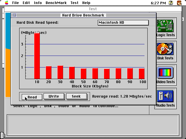
Next was my Mac IIcx. It booted System 7.5.3 with no problems, and booted a clean install of System 6.0.8 in about 5 seconds (years ago, the same machine booted 6.0.7 in about 9 seconds from hard drive). I ran some benchmarks in Snooper to see how it was running.
ALTALTALT
Read performance averaged about 1MB/s; Write performance was just under 0.5MB/s; and Seek times were virtually nonexistent.
Overall, I’m quite pleased. I’ve got it installed in an old external SCSI hard drive case at the moment so I can move between machines easily. I have multiple images set up, which properly mount as multiple SCSI hard drives. The only problems I’ve noticed so far is sometimes images aren’t recognized if their filenames are too long, and the device is eerily quiet in these old machines compared to the old hard drive noise.
It’s not as widely compatible as SCSI2SD, with only later 68000 Macs and most 68030 Macs officially supported, and initial support for Mac Plus recently announced. I don’t have an unsupported 68k Mac to test with, but I might connect it to my SuperMac c500 just to see what happens.
I’m hoping to order a few more kits. I would like to have one each to install in my SE, IIcx, and Classic.
This post was not sponsored in any way, and I have no connection with Eric Helgeson, creator of BlueSCSI.
I have a project I’m working on that needs an XT class machine, preferably at the original 4.77MHz.
I have an original IBM 5160 motherboard. It has a tantalum capacitor that is a direct short on the power supply. I also have an XT clone motherboard that I’ve successfully tested and booted a number of times.
I recently acquired a nearly complete XT clone system, but it was a 10MHz turbo XT, and missing its CPU. So I installed the known-good 4.77MHz XT clone board in the 10MHz clone case.
Flipped the switch and nothing happened. The power supply clicked like a switch mode supply failing to start up, so I quickly turned it back off. As the supply’s capacitors slowly discharged, it continued its death click until …
Pop goes the magic smoke.
I suspected the power supply at first. I’ve not had it as long, and those Rifa input filter capacitors are notorious for blowing at random times. Inside of the supply was surprisingly clean. No sign of damage, and thankfully, no sign of Rifa.
So turning attention to the motherboard, I found the culprit — a 16V tantalum filter capacitor across the 12V power supply. These too are notorious for blowing at random times.
I had picked up a VLB Diamond Stealth 64 video card at Computer Reset, so obviously I needed a VLB motherboard to put it to good use.
I picked up 5 bad VLB motherboards.
The first three I knew were not likely to work. They were rare early Pentium boards with both PCI and VLB, but all had the same Varta battery destruction. The other two were generic 486 boards that looked to be in great shape. Unfortunately, both had some unseen damage such that they would only run if flexed in just the right manner.
So I made the trek out to Computer Reset again.
I found one good-looking VLB board, an Asus this time. Unfortunately, no POST. It wouldn’t even get far enough to output a failure code on my POST card. I spent far too much time trying to get any sign of life out of it …
… before finally turning it over and realizing it had some pretty significant scrapes on the underside.
See, I had pulled it out of a large box of other boards. Who knows how long they had been there and where they had been before or who had dug through them already. At some point, something scraped across the back of this board and hurt it pretty badly.
I’ve never done any significant rework on a board like this, but it’s never too late to learn. I started by marking the scratches with a marker, then out came the scalpel and the continuity probes.
The first few wires were easy — short traces between the DIP sockets for cache RAM. Their endpoints were easy to see, and the pins were easy to solder to.
The others were a bit harder. First thing I had to do was scratch off some of the solder mask on either side of the scrape to confirm if continuity had indeed been broken. The traces were too close together for me to solder short bridge wires right across the gap, so I had to follow them back to vias or pins on either end.
When there that many traces that close together, they can be hard to follow. I like to take a fine-tip marker and draw a line following the trace all the way to the end. After I’ve soldered a wire in place, a little rubbing alcohol cleans up the marker, and I can move on to the next.
In this case, I was lucky that only a handful of traces were significantly broken. A few small scratches I was able to bridge with just solder, patching several nearby with a drag solder technique similar to that used for surface mount ICs.
Once I was done patching, I covered any areas with remove solder mask with clear nail polish. I tried dabbing a bit of hot glue on the ends of the wires to help them stay in place, but it didn’t really work well. Next time I’ll try something different (more nail polish has been recommended to me by some far more experienced techs).
In the end, the repair was successful. I was able to get it to boot right up after patching those few traces, and didn’t even have to break out the soldering iron a second time. I am quite pleased with how this turned out.
I’ve got some other odds and ends picked up from Computer Reset that should turn this into a nice machine. I’ve got it running currently with a 66MHz Intel 486DX2, 96MB RAM, the Diamond Stealth 64 VLB video card, and an EtherLink III. Somewhere I know I’ve got a SoundBlaster to round it out.
I’ve also got both an Intel and an AMD 100MHz DX4 that I would love to put in this machine. I’m interested to see if my patchwork will hold up to running the board at full speed.

 ALT
ALT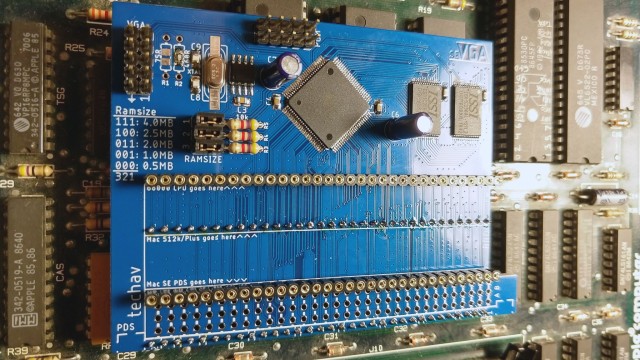 ALT
ALT ALT
ALT ALT
ALT ALT
ALT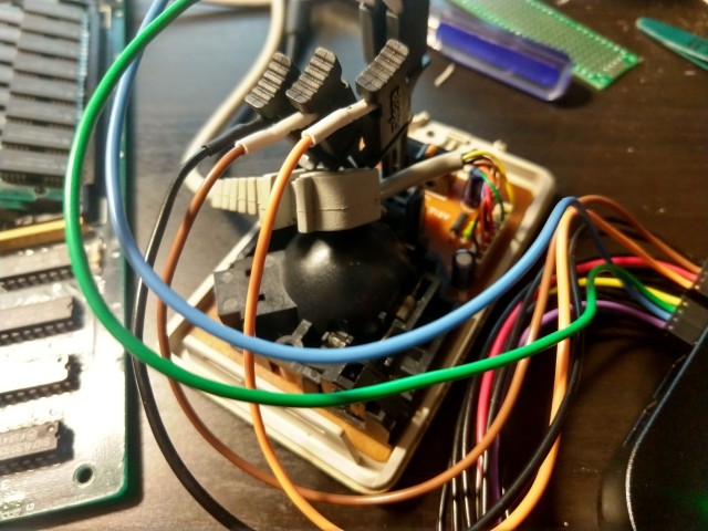 ALT
ALT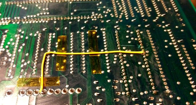 ALT
ALT ALT
ALT ALT
ALT ALT
ALT ALT
ALT ALT
ALT


 ALT
ALT ALT
ALT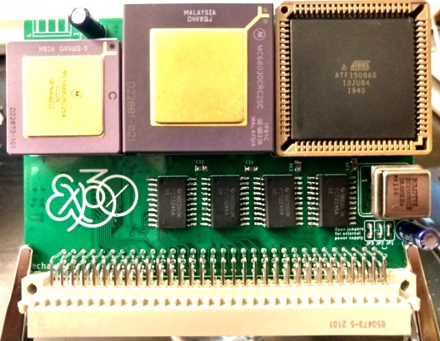 ALT
ALT ALT
ALT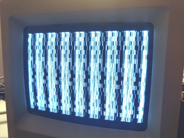 ALT
ALT ALT
ALT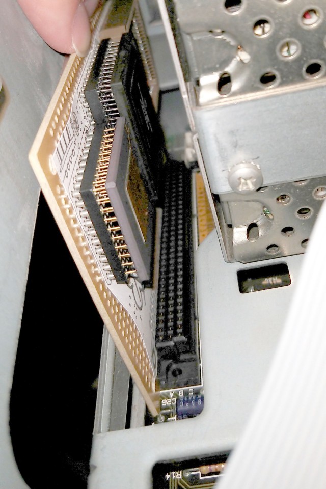 ALT
ALT ALT
ALT


 ALT
ALT ALT
ALT ALT
ALT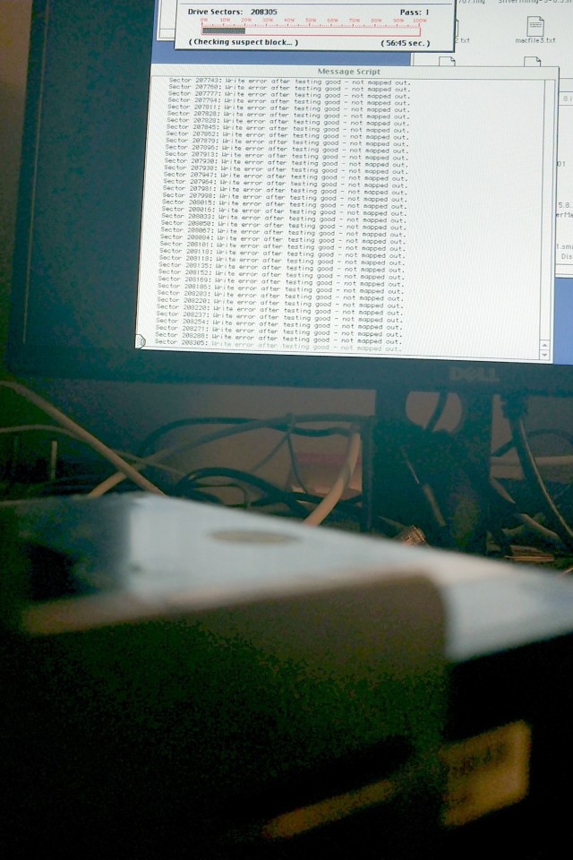 ALT
ALT

 ALT
ALT ALT
ALT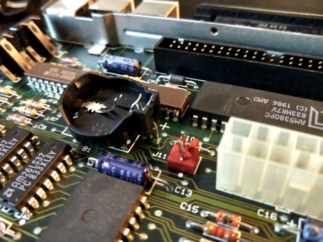 ALT
ALT ALT
ALT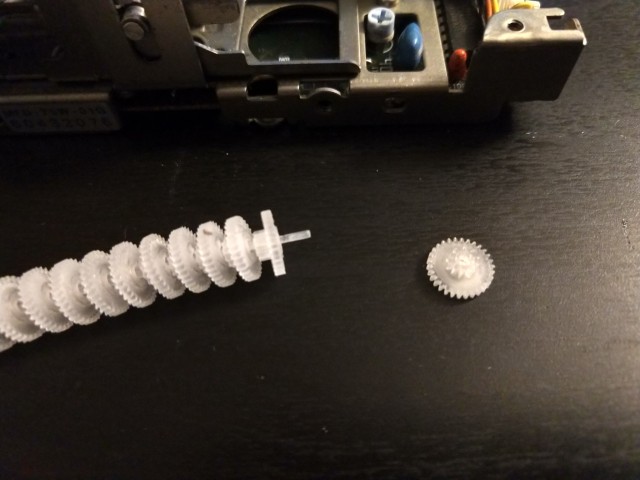 ALT
ALT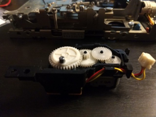 ALT
ALT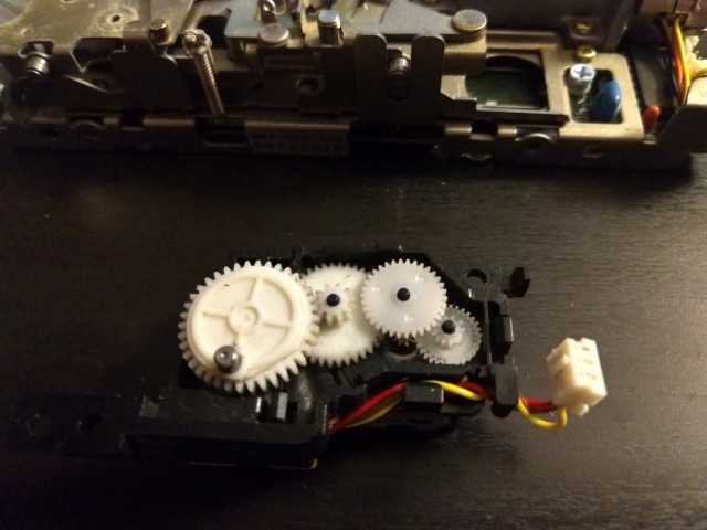 ALT
ALT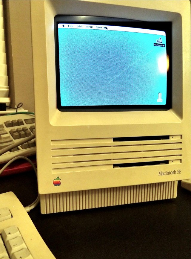 ALT
ALT

 ALT
ALT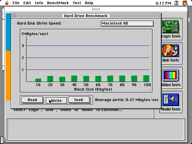 ALT
ALT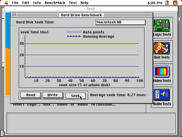 ALT
ALT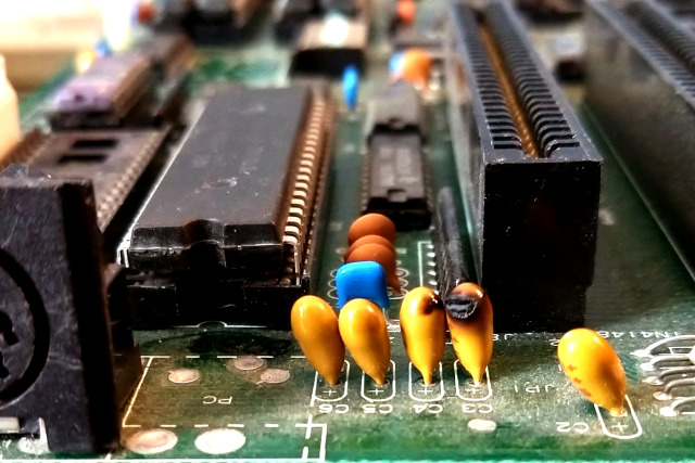 ALT
ALT