#retro computing


I was feeling nostalgic about some old computer games, and thought I’d have a go a re-creating Speedball 2 - Brutal Deluxe cover art in a different style. Hope you guys like it.
Post link


The Minitel was a Videotex online service accessible through telephone")
Matra Minitel Terminal (1984)
The Minitel was a Videotex online service accessible through telephone lines, and is considered one of the world’s most successful pre-World Wide Web online services.
The service was rolled out experimentally in 1978 in Brittany and throughout France in 1982 by the PTT (Postes, Télégraphes et Téléphones; divided since 1991 between France Télécom and La Poste). From its early days, users could make online purchases, make train reservations, check stock prices, search the telephone directory, have a mail box, and chat in a similar way to what is now made possible by the Internet.
Source:Wikipedia
Post link
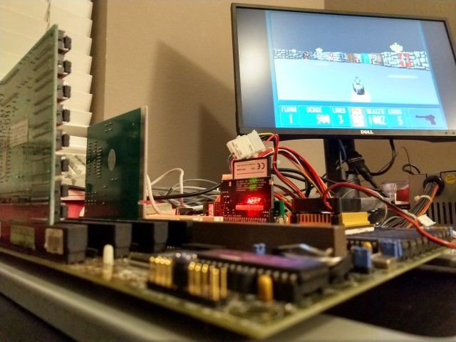
Debugging 68030 PCB

I had dared to hope that since this board was created from the same schematic and board file I had made and referenced for my wire-wrap 68030 project, that I could just move the parts over and let it run. If I was really lucky, it might even be able to run faster than the original.
I should know by now it’s never that easy.
The board does indeed run. It starts up, initializes its serial port, copies BASIC into RAM, verifies the copy, then starts running BASIC. It never gets to the BASIC ready prompt though.
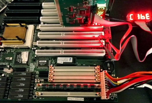
Time to pull out the logic analyzer. This would certainly be easier if I had a proper logic analyzer with 64 or even over 100 channels, but there is a lot that can be learned 16 channels at a time. Watching important parts of the address bus I was able to watch it step through the BASIC initialization routines. However just before it got to the point where it would print its first carriage return, it jumped to an address I didn’t expect, and I couldn’t follow where it had gone. Shortly after, it would start accessing invalid addresses and generating bus errors.
The point where I lost it was right when it called a vector to its character print subroutine. This version of BASIC is written to be position-independent, so it has a short vector table for common I/O handlers in its global variable space. When it’s time to call one of these routines, it performs a jump operation using the vector in that table ( jsr voutp(a3)).
I could see it getting that far, recall the vector, and push its return address to stack. But where it ended up was a mystery.
This points to memory corruption somewhere, but where? I had a similar issue when I was building the prototype, before I had properly built out the RAM chip select signals, but that fix is already incorporated into this board.
I started writing some memory test routines. Unsurprisingly, long word write and read back tests all passed (after all it was loading and verifying BASIC the same way already). Byte-level tests also passed without issue. I needed something more thorough.
I put together a simple test that would write a single byte, followed by writing a long word, alternating for 16 total bytes. This would force it to write misaligned long words to confirm RAM addressing was working correctly.
It failed.
The bytes read back were all jumbled, and a couple values were missing altogether. This really was looking like that old problem with the missing chip select signals, but I had already verified those were firing.
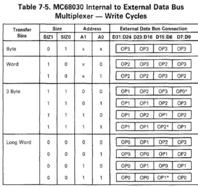
This chart from the 68030 manual shows what data will be output for any given write cycle. I went through my memory test one write at a time, writing down what would be present on the data bus and where for each cycle.
The random, nonsensical data read back from RAM immediately made sense. Where a byte write cycle should have written data to the lowest-order bits, the highest-order bits were getting saved, and vice versa.
My chip RAM chip select signals are indeed working — they’re just wired backwards.
Thankfully, that’s an easy fix. I used a CPLD for all the glue logic on this project, so all I really need to do is update the pin assignments for those four signals. I don’t even need a new board.
I might take this opportunity to further update the CPLD. I initially built out the logic for this project entirely in Quartus schematic view. I think I could do the same in System Verilog now. I suspect my old CPLD configuration may be partially responsible for my speed problems, so it may do some good to rewrite it.
Returning to 68030
It’s been two years now since I started my first foray into wire-wrap prototyping. My 68030 build, the state-of-my-art from 2019 has spent most of the last two years sitting in a box.
I had gotten it running BASIC at a quarter of the speed I had hoped for, and if the wind blew just right sometimes I could even get it to use the 68882 for maths. It worked, but only just. Too unstable for any further work. I had big plans for it, but could not continue without addressing its problems.
Well, finally, I have new progress. I ordered a PCB of the main board — exactly as it was laid out for the wire-wrap prototype.


My hope is that a proper board will help with the noise issues I was having with the wire-wrap board.
A couple hours soldering, and it was ready to move all the parts over from the prototype. Since it was made from the same schematic, and was indeed the same file I referenced for wiring the prototype, it should be that easy.
Fingers crossed it works at least as well as the prototype.

Only one way to find out …


Repairs
I had picked up a VLB Diamond Stealth 64 video card at Computer Reset, so obviously I needed a VLB motherboard to put it to good use.
I picked up 5 bad VLB motherboards.
The first three I knew were not likely to work. They were rare early Pentium boards with both PCI and VLB, but all had the same Varta battery destruction. The other two were generic 486 boards that looked to be in great shape. Unfortunately, both had some unseen damage such that they would only run if flexed in just the right manner.
So I made the trek out to Computer Reset again.
I found one good-looking VLB board, an Asus this time. Unfortunately, no POST. It wouldn’t even get far enough to output a failure code on my POST card. I spent far too much time trying to get any sign of life out of it …
… before finally turning it over and realizing it had some pretty significant scrapes on the underside.
See, I had pulled it out of a large box of other boards. Who knows how long they had been there and where they had been before or who had dug through them already. At some point, something scraped across the back of this board and hurt it pretty badly.
I’ve never done any significant rework on a board like this, but it’s never too late to learn. I started by marking the scratches with a marker, then out came the scalpel and the continuity probes.
The first few wires were easy — short traces between the DIP sockets for cache RAM. Their endpoints were easy to see, and the pins were easy to solder to.
The others were a bit harder. First thing I had to do was scratch off some of the solder mask on either side of the scrape to confirm if continuity had indeed been broken. The traces were too close together for me to solder short bridge wires right across the gap, so I had to follow them back to vias or pins on either end.
When there that many traces that close together, they can be hard to follow. I like to take a fine-tip marker and draw a line following the trace all the way to the end. After I’ve soldered a wire in place, a little rubbing alcohol cleans up the marker, and I can move on to the next.
In this case, I was lucky that only a handful of traces were significantly broken. A few small scratches I was able to bridge with just solder, patching several nearby with a drag solder technique similar to that used for surface mount ICs.
Once I was done patching, I covered any areas with remove solder mask with clear nail polish. I tried dabbing a bit of hot glue on the ends of the wires to help them stay in place, but it didn’t really work well. Next time I’ll try something different (more nail polish has been recommended to me by some far more experienced techs).
In the end, the repair was successful. I was able to get it to boot right up after patching those few traces, and didn’t even have to break out the soldering iron a second time. I am quite pleased with how this turned out.
I’ve got some other odds and ends picked up from Computer Reset that should turn this into a nice machine. I’ve got it running currently with a 66MHz Intel 486DX2, 96MB RAM, the Diamond Stealth 64 VLB video card, and an EtherLink III. Somewhere I know I’ve got a SoundBlaster to round it out.
I’ve also got both an Intel and an AMD 100MHz DX4 that I would love to put in this machine. I’m interested to see if my patchwork will hold up to running the board at full speed.
For now though, Wolfenstein.
Troubleshooting
Picked up this old 486 board from the parts room at Computer Reset in Dallas. I’ve got a VLB video card I would love to be able to use with it.
Unfortunately, this board has a short or some internal damage. It often fails POST with errors related to memory. However, if I flex the board or push on it just right, sometimes it will boot.
I’ve got another board, nearly identical to this one, with the same problem.
I think this one is beyond my current abilities to troubleshoot and repair.

Japanese Macintosh ad circa 1987. This illustration is often credited to Naoyuki Sato (or sometimes Kato). It is uncertain if that correct artist. Still a wonderful piece.
art image computer apple macintosh 1980s illustration postmodern architecture postmodernism postmodern japan japanese art naoyuki sato
Post link

Thank you for following!
I usually post a status update with milestone posts like this, although with how crazy life has been lately I don’t have much new to say. I’m still trying to switch into doing illustrations more. The difference this time is that I have a completely full sketchbook of illustrations so I’m a lot closer to it. (You can see some highlights in my monthly sketchbook posts)
Post link
")


")


