#aerodynamics


Shark Skin-Inspired Designs Improve Aerodynamic Performance
To build more aerodynamic machines, researchers are drawing inspiration from an unlikely source: the ocean.
A team of evolutionary biologists and engineers at Harvard University, in collaboration with colleagues from the University of South Carolina, has shed light on a decades-old mystery about sharkskin and, in the process, demonstrated a new, bioinspired structure that could improve the aerodynamic performance of planes, wind turbines, drones, and cars.
The research is published in the Journal of the Royal Society Interface.
Sharks and airplanes aren’t actually all that different. Both are designed to efficiently move through fluid (water and air), using the shapes of their bodies to generate lift and decrease drag. The difference is, sharks have about a 400-million-year head start on the design process.
“The skin of sharks is covered by thousands and thousands of small scales, or denticles, which vary in shape and size around the body,” said George Lauder, the Henry Bryant Bigelow Professor of Ichthyology and professor of biology in the Department of Organismic and Evolutionary Biology, a co-author of the research. “We know a lot about the structure of these denticles — which are very similar to human teeth — but the function has been debated.”
Post link

Hans Erni, ink on glassine paper, ca. 1935, private collection, © Hans Erni Estate.
Hans Erni (1909–2015) designed this drawing for his friend Paul Jaray. He used this schematic representation of laminar and turbulent flow in several publications. Paul Jaray (1889–1974) was the first and most important pioneer of aerodynamics for automobiles. Via Nero
Post link
")


Bending light using heat: DIY Airplane edition
These images were captured from an airplane overlooking San Fransisco. But there’s something interesting going on here and something you can try the next time you are flying.
Right near the the middle of the image you should be able to notice a haze in the image. This is due to the exhaust from the engine.

Hot air is less dense than cold air.
And this creates a gradient in the refractive index of the air.
The turbulence of the air emanating from the exhaust gases also has a direct correlation to the degree of distortion of the image.
More the turbulence, more the distortion.
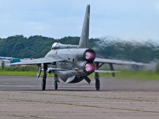
Although the above image is from a commercial aircraft, the effect is even more dramatic in fighter jets.
* The term that is used to describe this phenomenon is ‘Heat Haze’. You can read more about this here.
Post link

This week NASA released the first-ever image of shock waves interacting between two supersonic aircraft. It’s a stunning effort, requiring a cutting-edge version of a century-old photographic technique and perfect coordination between three airplanes – the two supersonic Air Force T-38s and the NASA B-200 King Air that captured the image. The T-38s are flying in formation, roughly 30 ft apart, and the interaction of their shock waves is distinctly visible. The otherwise straight lines curve sharply near their intersections.
Fully capturing this kind of behavior in ground-based tests or in computer simulation is incredibly difficult, and engineers will no doubt be studying and comparing every one of these images with those smaller-scale counterparts. NASA developed this system as part of their ongoing project for commercial supersonic technologies. (Image credit: NASA Armstrong; submitted by multiple readers)
How do these images get captured?
It may not obvious as to how this image was generated because if you have heard about Schlieren imaging what you have in your head is a setup that looks something like:
But how does Schelerin photography scale up to capturing moving objects in the sky?
Heat Haze
When viewing objects through the exhaust gases emanating from the nozzle of aircrafts, one can observe the image to be distorted.

Hot air is less dense than cold air.
And this creates a gradient in the refractive index of the air
Light gets bent/distorted
Method-01 : BOSCO ( Background-Oriented Schlieren using Celestial Objects )
You make the aircraft whose shock-wave that you would like to analyze pass across the sun in the sky.
You place a hydrogen alpha filter on your ground based telescope and observe this:

Notice the ripples that pass through the sunspots
The different air density caused by the aircraft bends the specific wavelength of light from the sun. This allows us to see the density gradient like the case of our heat wave above.
We can now calculate how far each “speckle” on the sun moved, and that gives us the following Schlieren image.

Method-02: Airborne Background Oriented Schlieren Technique
In the previous technique how far each speckle of the sun moved was used for imaging. BUT you can also use any textured background pattern in general.
An aircraft with camera flies above the flight like so:

The patterned ground now plays the role of the sun. Some versions of textures that are commonly are:

The difficulty in this method is the Image processing that follows after the images have been taken.
And one of the main reasons why the image that NASA has released is spectacular because NASA seems to have nailed the underlying processing involved.
Have a great day!
* More on Heat hazes
** More on BOSCO
*** Images from the following paper : Airborne Application of the Background Oriented Schlieren Technique to a Helicopter in Forward Flight
**** This post obviously oversimplifies the technique. A lot of research goes into the processing of these images. But the motive of the post was to give you an idea of the method used to capture the image, the underlying science goes much deeper than this post.
Post link
The land speed record stagnates at 1997.
This says more than it should.
all the new land speed records are like using solar power or whatever. that’s just the state at which transportation is at now – refinement
Well, the records went way past where pushing them further contributed anything to the development of land transport, or engineering in general (to the extent at this point they’re basically airspeed records with the oddball qualifier of being achieved in contact with the ground) and no one particularly wants to spend their money or passion on it
Is there a requirement of how much weight has to be on the wheels? If not, you could use a supersonic jet plane with a long extensible arm and a tungsten skate on the end of the arm. The jet flies at Mach 2, a few feet above the course, dragging the skate along the ground. The skate gets white hot, but as long as the wheels still spin we’re OK.
The existing record holders are all jet propelled devices, which are not planes only because their designers expended effort to make sure the aerodynamic forces push down.
Few feet off you’d be dealing with ground effect and weird interaction of the transsonic airflow with the ground
Assuming Mach 2, as long as your height is more than half your length, you wouldn’t notice the ground. The bow shock would be reflected from the ground and come back up, but by then you would have gone past. The skate and supporting arm would get tangled in the shocks, but they’re small so forces are minor.
Unless the shock plus reflection forms a Mach stem that rises too high. Is there a supersonic aerodynamicist in the house?

")

