#computer repair

Franken-Plus
I have an old Mac Plus that was given to me nearly 25 years ago. For as long as I’ve had it, it has not been a functional computer.
 ALT
ALTOver the years I’ve robbed it for parts for other projects — sometimes rather destructively. One serial port was sawed off in my early teenage years, the other was clearly desoldered much later. The serial chip was removed for my first Z80 homebrew. The 68000 CPU was used for my first 68k homebrew. The oscillator was removed for other homebrew projects. Remaining parts were marked for whether they were generic or proprietary, so I could know whether they would be useful for future projects.
Every part I’ve removed from this board has been functional. When we tested the machine 25 years ago, it did not power on or show any other signs of life. Knowing what I do now, it’s obvious to me that it had a bad analog board, but the logic board was probably still good.
I think it’s time to breathe new life into this abused machine. Luckily, I still have the parts I removed from it.
One of the goals of my SE-VGA project is to support older classic Macs that whatever reason no longer have functional CRTs. I of course had this old Plus in mind all along when designing that into the SE-VGA. As soon as I knew the Rev 2 boards were functional, I assembled one with 68000 CPU headers instead of the SE PDS connector.
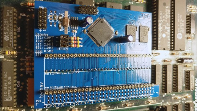 ALT
ALTSince the analog board for this Plus is bad, I’ll need some other way to interface with a monitor. The SE-VGA board will allow me to use any VGA monitor in place of the original CRT.
The analog board is also the power supply for the Plus, so I’ll need a new power supply as well.
 ALT
ALT ALT
ALTI have an old XT era power supply with a similar connector to the analog connector on the Plus motherboard. It’s a standard Molex part with removable crimp-on contacts. It was fairly easy to remove all the contacts and rearrange them to match the layout required to power the Plus motherboard.
The board powered on, the SE-VGA output its video, but the Plus was not happy. Every time it powered on, it gave Sad Mac error 02FFFF. This code means it passed the ROM checksum, but it was failing the first RAM test. The FFFF on the error code would indicate that every RAM chip was bad. Since it gave the same error with or without RAM installed, and with known-good RAM installed, the problem is clearly elsewhere.
 ALT
ALTI started by probing the data path between the CPU and RAM. Data was making its way through the buffers, and as best as I could tell RAM and the DRAM control state machine were working properly. So I turned to a disassembly of the ROM to see what it was actually testing.
The first RAM test starts at address $00,0000, writes data, then reads it back. Then it moves to address $00,0001,$00,0002,$00,0004,$00,0008,$00,0010, etc. It’s not really testing the data bus here, it’s testing the address bus, looking for stuck address signals. So I started probing the address multiplexers. Every CPU address signal to the RAM was accounted for except A1.
When the 68000 CPU was removed from this board, the pad for A1 was damaged. A hairline crack separated the pad from its trace. A quick bodge wire, and no more Sad Mac.
The next problem I encountered was an interesting one. The insert disk icon — a floppy disk with a blinking question mark — wasn’t blinking. This time, The Dead Mac Scrolls held the answer: early Macs without a floppy drive connected won’t blink the question mark.
So I pulled an 800k floppy drive from my SE and plugged it in. On power up, the eject motor spun up … and continued spinning.
[Sark] had the answer for this one. There are a few different versions of floppy drives Apple used. They are compatible, but using newer drives in older computers sometimes requires a specific cable (the yellow stripe cable) which cuts pins 9 & 20. One custom cable later, no more constantly-running eject motor, and the question mark blinks as expected.
I don’t currently have any 800k bootable floppy disks, so I ordered a new BlueSCSI. The latest BlueSCSI revision supports the Mac Plus, and indeed booted right up without issue.
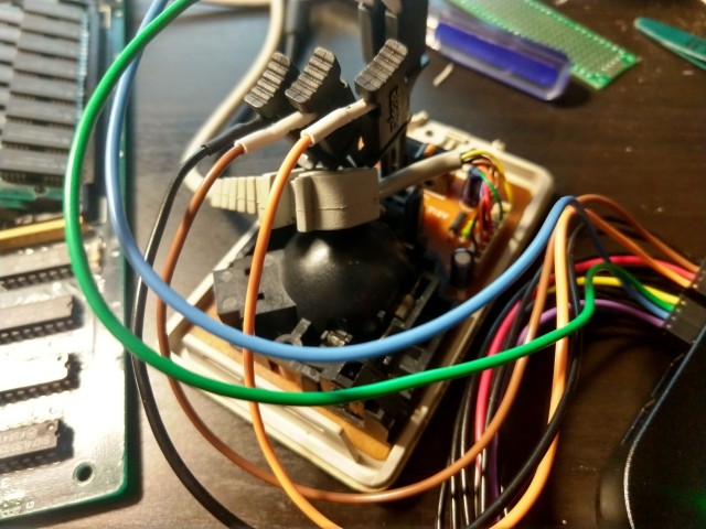
But once booted, the mouse didn’t work. It would only move vertically, not horizontally. Logic analyzer showed the mouse was properly outputting quadrature signals from the rotary encoders, but the computer wasn’t responding to them. Back to the schematics, tracing the signals and sure enough, another broken trace and another bodge wire.
 ALT
ALT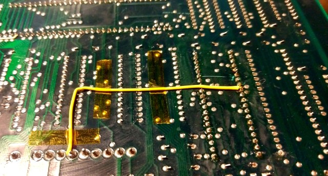 ALT
ALTFinally, there was only one thing left to do — build a keyboard cable. The early Macs used a cable that looks like the handset cable on an old analog telephone, but the keyboard cables were wired straight through instead of crossed like the phone cables. I had to order the proper terminations and tool, but had no problems assembling it.
It was a lot of work, and required pulling together many different parts and pieces, but finally this old Mac Plus lives again.
 ALT
ALTA Quick Fix
 ALT
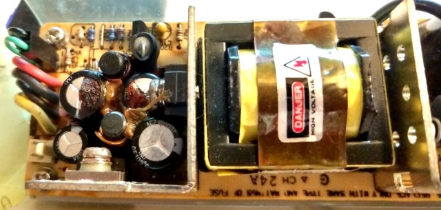
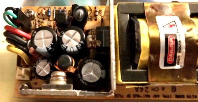
ALTI have a 1996 LaCie Tsunami 9GB external SCSI hard drive. It actually works just fine, but there are a couple filter capacitors on the output stage of its power supply that have leaked. I had some equivalent replacements on hand from previous repairs, so it took no time at all to replace them.
 ALT
ALTHopefully this will keep this power supply humming along well filtered for another quarter century.
Repairing a Mac SE
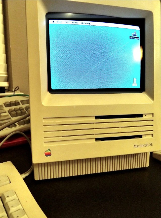
I picked up an old Mac SE that had a bit of a problem: terrible distortion and interference appearing as horizontal lines on the monitor. It otherwise boots without issue, so the problem is most likely on the analog board.
With these old Macs, it’s common to find capacitors have failed and leaked, often wreaking havoc on the boards in the process. This machine though was surprisingly clean. There were none of the telltale signs of leaked capacitor electrolyte on the top of the analog board. The connectors were all clean, with no sign of corrosion.
Removing the analog board, and the plastic insulator attached to it, did not immediately indicate the cause either. There did end up being one capacitor that had leaked through the back side of the board, but it was part of the -5V power supply, and was not involved with the video circuitry.
It took a magnifying glass and bright light at just the right angle to find the problem. There was a hairline crack in the solder around the horizontal deflection pin on the yoke connector. It was not immediately obvious, and did not appear to even follow all the way around the joint. Nevertheless, it was enough to cause problems.
I carefully reflowed the solder joints around all of the yoke connector pins and the flyback transformer, taking care to wick away much of the old solder and replace with new. Replacing the solder is a largely unnecessary step, but it ensured that the joint was well heated to prevent a cold joint, and introduced some new flux to help the solder flow properly. While I had it out, I also cleaned up and replaced the one failed capacitor on the -5V supply.
 ALT
ALTSuch a tiny fix, but with a huge effect. The image is now completely stable.
This machine does need a little more work. Both of its floppy drives need cleaning and new eject gears. This unit also had been upgraded with an aftermarket internal hard drive that needs further testing. I may go ahead and replace the drive with a BlueSCSI. Finally, it only has 2.5MB of memory, so a couple new 1MB SIMMs will bring it up to a much more usable 4MB.
After that, it’s time to have some fun with that PDS slot. I’ve got a Full Page Display video card to try out, and I’d like to try my hand at building a processor accelerator card.
Thanks to Sark and jbevren for help diagnosing the video issues on this SE.


Repairs
I had picked up a VLB Diamond Stealth 64 video card at Computer Reset, so obviously I needed a VLB motherboard to put it to good use.
I picked up 5 bad VLB motherboards.
The first three I knew were not likely to work. They were rare early Pentium boards with both PCI and VLB, but all had the same Varta battery destruction. The other two were generic 486 boards that looked to be in great shape. Unfortunately, both had some unseen damage such that they would only run if flexed in just the right manner.
So I made the trek out to Computer Reset again.
I found one good-looking VLB board, an Asus this time. Unfortunately, no POST. It wouldn’t even get far enough to output a failure code on my POST card. I spent far too much time trying to get any sign of life out of it …
… before finally turning it over and realizing it had some pretty significant scrapes on the underside.
See, I had pulled it out of a large box of other boards. Who knows how long they had been there and where they had been before or who had dug through them already. At some point, something scraped across the back of this board and hurt it pretty badly.
I’ve never done any significant rework on a board like this, but it’s never too late to learn. I started by marking the scratches with a marker, then out came the scalpel and the continuity probes.
The first few wires were easy — short traces between the DIP sockets for cache RAM. Their endpoints were easy to see, and the pins were easy to solder to.
The others were a bit harder. First thing I had to do was scratch off some of the solder mask on either side of the scrape to confirm if continuity had indeed been broken. The traces were too close together for me to solder short bridge wires right across the gap, so I had to follow them back to vias or pins on either end.
When there that many traces that close together, they can be hard to follow. I like to take a fine-tip marker and draw a line following the trace all the way to the end. After I’ve soldered a wire in place, a little rubbing alcohol cleans up the marker, and I can move on to the next.
In this case, I was lucky that only a handful of traces were significantly broken. A few small scratches I was able to bridge with just solder, patching several nearby with a drag solder technique similar to that used for surface mount ICs.
Once I was done patching, I covered any areas with remove solder mask with clear nail polish. I tried dabbing a bit of hot glue on the ends of the wires to help them stay in place, but it didn’t really work well. Next time I’ll try something different (more nail polish has been recommended to me by some far more experienced techs).
In the end, the repair was successful. I was able to get it to boot right up after patching those few traces, and didn’t even have to break out the soldering iron a second time. I am quite pleased with how this turned out.
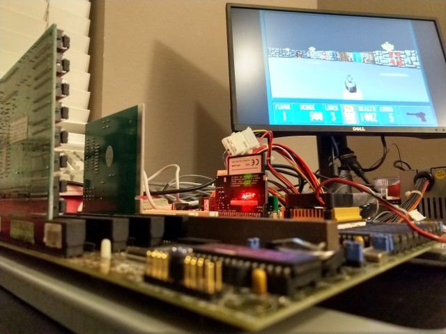
I’ve got some other odds and ends picked up from Computer Reset that should turn this into a nice machine. I’ve got it running currently with a 66MHz Intel 486DX2, 96MB RAM, the Diamond Stealth 64 VLB video card, and an EtherLink III. Somewhere I know I’ve got a SoundBlaster to round it out.
I’ve also got both an Intel and an AMD 100MHz DX4 that I would love to put in this machine. I’m interested to see if my patchwork will hold up to running the board at full speed.
For now though, Wolfenstein.